


24
C048-725-30 Rev. B (01/2020)
8.0
8.0
Product Specifications
Product Specifications
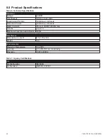
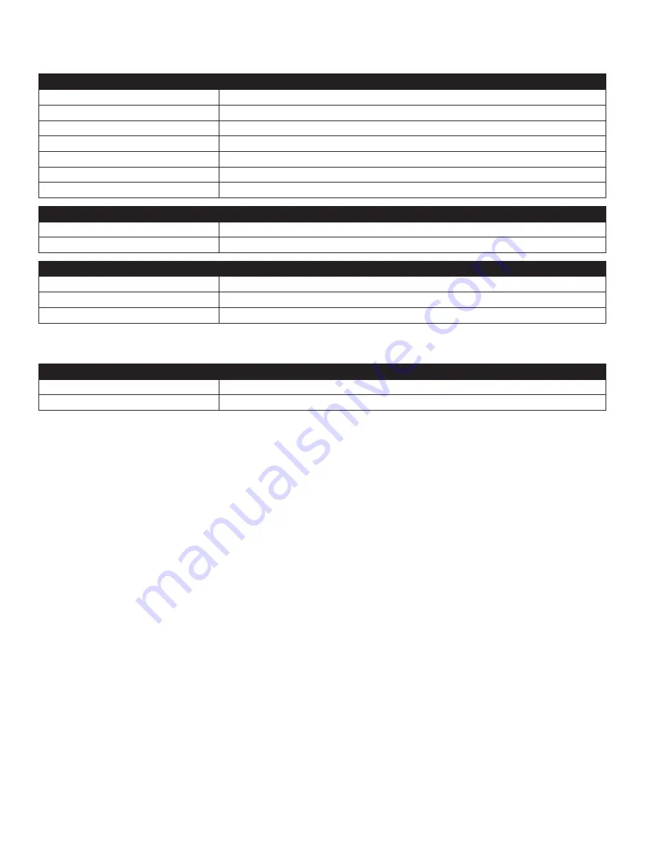
Table 6.
Technical Specifications
Electrical
Voltage
-48VDC
Input Busses
Single or dual (A/B)
Load Current Per Bus
320A max� continuous
Total Load Current
320A max� continuous
Alarm Contacts
Form-C, 60VDC @ 0�5A max
Circuits
Up to 16
Maximum Input Interruption Device 400A
Mechanical
Dimensions L x H x D
17 x 1�75 x 16�5
Weight
8�5
Environmental
Operating Temperature
0 to 50°C
Humidity
0 to 95% RH non-condensing
Elevation
-500 to 3000m
Table 7.
Agency Certifications
UL
UL File Number
E473904
UL Standard
ANSI/UL 60950-1
Summary of Contents for alpha Matrix C16
Page 31: ......


