background image

171 435 42  16-01

ELECTRIC EQUIPMENT

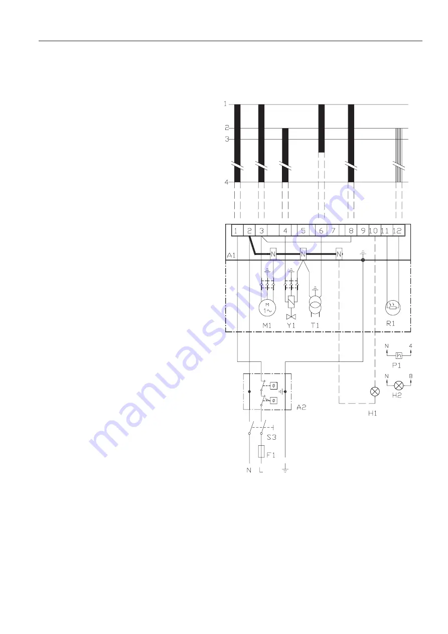
Oil burner control: LOA24..

List of components

A1  Oil burner control
A2  Twin thermostat
F1  Fuse, max. 10A
H1  Alarm lamp
H2  Signal lamp (optional)
M1  Burner motor
P1  Time meter (optional)
R1 Photoresistor
S3  Main switch
T1  Ignition transformer
Y1  Solenoid valve

Mains connection and fuses in 
accordance with local regulations.

Wiring diagram

1(2)

Summary of Contents for Bentone B40 CN

Page 1: ...Providing sustainable energy solutions worldwide 178 032 53 2 2016 07 08 Installation and maintenance instruction B40 CN...

Page 2: ......

Page 3: ...y 5 Ignition cable 6 Ignition transformer 7 Photo cell 8 Control box 9 Reset button 10 Cover inspection glass 11 Fan wheel 12 Motor 13 Nozzle assembly adjustment 14 Blast tube 15 Air adjustment 16 Air...

Page 4: ...deinite spray angle or spray pattern Recommended nozzle Output range and nozzles recommended The net caloriic value of 11 86 kWh kg for light oil has been used Burner tube Length of burner tube Measu...

Page 5: ...s fol lows Increase the nozzle assembly adjustment somewhat The CO2 con tent and consequently the air volume will then be reduced GENERAL INSTRUCTIONS Condensation in chimney A modern burner works wit...

Page 6: ...ch off power at the main switch and cut off the oil supply Open the cover and disconnect the connecting pipes by loosening screw A Service of burner head 1 Loosenorswingouttheburner from the boiler 2...

Page 7: ...l burner control A2 Twin thermostat F1 Fuse max 10A H1 Alarm lamp H2 Signal lamp optional M1 Burner motor P1 Time meter optional R1 Photoresistor S3 Main switch T1 Ignition transformer Y1 Solenoid val...

Page 8: ...e burner will make an attempt to re start 3 4 Operating position If the burner operation is interrupted by means of the main switch or the thermostat a new start takes place when the conditions in acc...

Page 9: ...blesapplytoastandardfueloilof normal commercial quality according tocurrentstandards Oncommissioning with an empty tube system the oil pump should not be run without oil for more than 5 min a conditio...

Page 10: ...f the pump is overloaded i e If you try to get out more oil than the gear setcansupplyunderexistingcircum stances the oilpressurefallsbelowthe setvalue andthevalveclosesagainst 171 505 10 10 01 Replac...

Page 11: ...93 9 71 115 99 10 24 121 104 10 73 127 109 3 00 9 98 118 102 10 59 126 108 11 16 132 114 11 71 139 119 3 50 11 65 138 119 12 35 146 126 13 03 154 133 13 66 162 139 4 00 13 31 158 136 14 12 167 144 14...

Page 12: ...1 21 133 114 11 67 138 119 12 11 144 123 12 53 148 128 3 00 12 23 145 125 12 73 151 130 13 21 157 135 13 67 162 139 3 50 14 27 169 145 14 85 176 151 15 42 183 157 15 95 189 163 4 00 16 31 193 166 16 9...

Page 13: ...f magnetic valve Burner fails to start Lamp not lit Motor runs Burner runs to lockout Fuse has blown Appliance thermostat has not reset Appliance overheat device has operated Control relay or photocel...

Page 14: ......

Page 15: ...the burner will not start Press the reset button on the relay Check that the thermostats are correctly adjusted Don t forget the room thermostat check that any fusesare intact and main switch is on If...

Page 16: ......

Page 17: ......

Page 18: ......

Page 19: ......

Page 20: ...Enertech AB P O Box 309 SE 341 26 Ljungby www bentone se www bentone com...

Reviews: