background image

Providing sustainable energy solutions worldwide

178 005 82-2    2016-05-10

Installation- and maintenance instruction

BG 550 CN, BG 650 CN

Model 2, M

BG 550 LN CN

Summary of Contents for Bentone BG 550 CN

Page 1: ...Providing sustainable energy solutions worldwide 178 005 82 2 2016 05 10 Installation and maintenance instruction BG 550 CN BG 650 CN Model 2 M BG 550 LN CN...

Page 2: ......

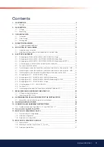
Page 3: ...disruption disruption display Gas burner control LME ________________ 23 6 9 Wiring diagram LFL1 BG550 BG650 2 Steg_________________________________________________________________ 25 6 10 Wiring dia...

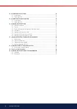
Page 4: ...______________________________________________________________________________ 52 16 6 Adjustment of min gas pressure switch____________________________________________________________________________...

Page 5: ...iler s components can exceed 60 C Check that the guide stop is installed before servicing Take great care when servicing Trap and pinch risks can be present The boiler s sound level can exceed 85 dBA...

Page 6: ...ozzle 9 Ionisation electrode 10 Motor 11 Connection gas ittings 12 Ignition transformer 13 Air damper 14 Air damper motor 15 Air pressure switch 16 Fuse holder 17 Indicating lamp Stage 2 18 Switch I I...

Page 7: ...ode 10 Motor 11 Connection gas ittings 12 Ignition transformer 13 Air damper 14 Air damper motor 15 Air pressure switch 16 Fuse holder 17 Change over switch increase decrease 18 Change over switch man...

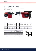
Page 8: ...ure B Burner tube Measure C Burner tube Measure D Length of burner tube Flange Measure B Burner tube Measure C Burner tube Measure D Standard 1 256 226 162 162 252 222 162 162 Standard 2 356 326 162 1...

Page 9: ...kV Ampl 50 mA rms 33 ED in 3 min 1 Caloriic value kWh m3 15 C 1013 25 mbar according to EN676 2 Dimension and capacity depending on gas quality and available pressure Capacity kW Gas volume at a min o...

Page 10: ...W 100 200 300 400 500 600 700 2 0 6 8 12 4 2 Capacity kW 200 300 400 500 600 700 800 2 0 6 8 10 12 14 4 2 Pressure in ire place 16 900 1000 1100 1200 3 3 Working field BG550 140 640 kW BG550 BG550 G25...

Page 11: ...auge with shut off cock 5a Gas pressure switch mini 5b Gas pressure switch maxi 6a Main valve 2 stage 6b Safety valve 1 7 Valve proving system 8 Air damper motor 9 Air pressure switch 10 Gas burner co...

Page 12: ...n the screws B on both sides Loosen the stop bolt C on the pull rods Loosen the ignition cable and the ionisation cable from the gas assembly Pull out the burner on the pull rods and put it in a suita...

Page 13: ...sc in the blast tube Sometimes it is necessary to adjust the position of the shrouded disc in the blast tube This can be done with the screw E can be adjusted when the burner is in operation If you tu...

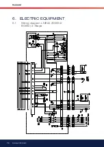
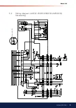
Page 14: ...14 Bentone BG550 650 General 6 ELECTRIC EQUIPMENT 6 1 Wiring diagram LME22 BG550 BG650 2 Stage...

Page 15: ...15 Bentone BG550 650 General Design without A3 6 2 Wiring diagram LME22 BG550 BG550LN BG650 Modulating...

Page 16: ...16 Bentone BG550 650 General Design without A3 6 3 Wiring diagram LME22 BG550 BG550LN BG650 Modulating with R316...

Page 17: ...tch S2 Operating switch stage 2 S3 Control thermostat S4 Temperature limiter S5 Micro switch for hinged door S6 Control thermostat stage 2 S7 Main switch 3 phase S8 Air pressure switch S11 Change over...

Page 18: ...n The gas is ignited The ionization electrode indicates a lame 4 The safety time expires The ignition spark goes out The safety time expires If there is no lame or if for some reason the lame disappea...

Page 19: ...or lame signal Flashinggreen Prohibited lame signal during start up Green Red Undervoltage Yellow Red Disruption alarm Red Flashing code for fault codes Flashing red Interface diagnostics Red lickerin...

Page 20: ...utton 0 5 3 s Alarm control table Red flashing code on signal lamp LED Possible causes Flashing 2 x No lame at End of TSA Defective or obscured lame monitor Defective or obscured fuel valves Poor burn...

Page 21: ...21 Bentone BG550 650 General DAMPER POSITION 6 7 Wiring diagram LFL1 BG550 BG650 2 Steg Design without A3 Design without S10...

Page 22: ...22 Bentone BG550 650 General DAMPER POSITION Design without A3 Design without S10 6 8 Wiring diagram LFL1 BG550 BG550LN BG650 Modulating...

Page 23: ...23 Bentone BG550 650 General Design without A3 DAMPER POSITION Design without S10 6 9 Wiring diagram LFL1 BG550 BG550LN BG650 Modulating with R316...

Page 24: ...24 Bentone BG550 650 General DAMPER POSITION Design without A3 Design without S10 6 10 Wiring diagram LFL1 BG550 BG650 2 stage 1 2...

Page 25: ...Main switch 3 phase S8 Air pressure switch S10 Gas pressure switch max S11 Change over switch Aut man S12 Change over switch Increase Reduce S20 Main switch 1 phase T1 Ignition transformer X1 Connect...

Page 26: ...n The gas is ignited The ionization electrode indicates a lame 5 The safety time expires The ignition spark goes out The safety time expires If there is no lame or if for some reason the lame disappea...

Page 27: ...ause no lame signal has been received on completion of the 1st safety time Any flame signal failure after completion of the first safety time also causes the control to go to lockout Interruption of t...

Page 28: ...water or a leak location spray After tightening repeat the test Electric function test Ensure that phase and neutral are not reversed The gas shut off cock should be closed To prevent the gas pressur...

Page 29: ...29 Bentone BG550 650 General Inner assembly Biogas UV detector Inner assembly Town gas Inner assembly Natural gas LPG...

Page 30: ...30 Bentone BG550 650 General A B A B 7 2 Inner assembly BG 550LN A 10 mm Front edge Brake plate B 3 mm A Position Ionisation detector B Position Ignition electrode...

Page 31: ...Temperature of the gas at the gas meter 15 C B Barometer height 945 mbar Pu Pressure of the gas at the gas meter 15 0 mbar f 273 15 1013 25 273 945 15 f 11 1 The gas volume read on the gas meter actu...

Page 32: ...e fast opening with max low adjustment 1 Protection cover 2 Flow adjustment 3 Lock nut Flow adjustment MVD 5 Remove protection cover 1 Loosen lock nut 3 Turn the low adjustment screw 2 to the right ga...

Page 33: ...DMV 505 520 11 Pressure taps 1 2 3 4 Sealing plug Screw plugs 1 2 3 may also be replaced by a measuring socket G 1 8 DIN ISO 228 Concealed connecting bore for sys tem accessories 10 OPERATION AND ASSE...

Page 34: ...ugs 1 2 3 and 5 may also be replaced by a measuring socket G 1 8 DIN ISO 228 1 Loosen screws A and B do not remove Figs 1 and 2 2 Remove screws C and D Figs 1 and 2 3 Remove double solenoid valve betw...

Page 35: ...e V1 during operation Check setting values continuously Smallest setting volume low 7 DMV DLE Rapid stroke adjustment V start Factory setting DMV DLE Rapid stroke not adjusted 7 1 Unscrew the adjustme...

Page 36: ...ed 8 9 Coat countersunk screw A with locking varnish 8 10 Leakage test Pressure tap at sealing plug 2 DMV 507 520 11 Pressure tap at sealing plug 3 DMV 525 11 p max 500 mbar 8 11 Perform functional te...

Page 37: ...mensions mm Max operating pressure 500 mbar Pressure regulator Klass A Ambient temperature 15 C 70 C Inlet pressure range 5 500 mbar Family 1 2 3 Outlet pressure range 2 5 200 mbar 1 Never close vent...

Page 38: ...91 500 Rp 3 4 100 130 28 165 G1 4 G1 4 G1 8 245 1 00 FRS 510 070 409 500 Rp 1 110 145 33 190 G1 4 G1 4 G1 8 310 1 20 FRS 515 058 446 500 Rp 1 1 2 150 195 40 250 G1 2 G1 4 G1 4 365 2 50 FRS 520 058 628...

Page 39: ...Adjustment Setting spindle B Turn clockwise Reducing outlet pressure setpoint 3 Check setpoint 4 Screw on protective cap A Replace setting spring 3 4 1 Remove protective cap A Release spring by turni...

Page 40: ...tment of stage 2 7 Lock screw for low adjustment 8 Main valve 9 Knob for adjustment of stage 1 10 Test nipple inlet pressure 11 Test nipple pressure after governor 12 Test nipple before governor 13 Fi...

Page 41: ...tighten the lock screw again 12 2 Adjustment of governor Adjust outlet pressure from governor by means of a screw driver Min and max outlet pressures correspond to appr 60 turns of the spring It is n...

Page 42: ...tio PBr PL max load 10 Test point connection 1 8 before V1 before governor 11 Connection M4 for measurement of burner pressure after V2 12 Adjustment screw for zero point adjustment N min load 13 Test...

Page 43: ...N 40050 Gas family 1 2 3 Outlet pressure 0 5 100 mbar Zero point adjustment N 2 mbar Pressure switch DIN3398 TI Fan pressure PL0 4 100 mbar Fire room pressure PF 2 5mbar Burner pressure PBr 0 5 100 mb...

Page 44: ...the air volume Turn orange cam towards 0 Increase the air volume Turn orange cam towards 90 Adjust the operating switch back to low load and check the air volume Full load Adjust the operating switch...

Page 45: ...dle does not licker increase N When the lame is established adjust the gas low by means of the screw N Use a lue gas instrument Change over to max load press the switch increase Adjust the gas low wit...

Page 46: ...eady for start up Howerer study the sections dealing with adjustments of multi bloc combustion air and combustion head Open the ball valve and switch on the main switch If the burner starts the actual...

Page 47: ...required ionisation current according to table In practice this current must be considerably higher preferably more than 10 A All the gas burners are equipped with a ionisation cable that can be slit...

Page 48: ...the gas pressure is too low and prevent the burner from starting Too low a gas pressure during operation should stop the burner The burner may start again when the rated gas pressure has been reached...

Page 49: ...sed to the control box after approx 30 s and the yellow LED lights up If the test section is leaky or if the pressure increase by 20 mbar is not attained during the test period max 26 s the VPS 504 ge...

Page 50: ...er Motor pump Solenoid valve Differential pressure sensort Release signal Controller Motor pump Solenoid valve Differential pressure sensor Release signal Controller Motor pump Solenoid valve Solenoid...

Page 51: ...al troubles Trouble free operation is depending on three factors electricity gas and air supply Should there be any changes in the ratio between these three factors there is a risk of break downs It h...

Page 52: ...br leur recevra le marquage CE de conformit Ljungby Sweden 141127 27 11 14 ENERTECH AB Bentone Division Box 309 SE 341 26 Ljungby Sweden H kan Lennartsson Enertech AB declares that the above mentione...

Page 53: ...t Cause Remedy The burner does not start No gas Check that all gas cocks are open No voltage Check fuses thermostats and electrical connections The burner motor fails to start The thermal protection h...

Page 54: ...ty authorities The ignition electrodes are disturbing the ionisation current Adjust the ignition electrodes repole the ignition transformer if necessary Bad earthing Arrange for proper earthing Phase...

Page 55: ...transformern Bad combustion Bad draught conditions Check the chimney The lue gas temperature is too high The boiler is overloaded Reduce the quantity of gas The CO2 content is too low Check the boile...

Page 56: ...en inte l st ut 3 Kontrollera andra termostater ex rumstermostat om s dan inns 4 Kontrollera att tillr ckligt gastryck inns till br nnaren 5 Unders k att de elektriska s kringarna r hela 6 Kontrollera...

Page 57: ...ire room Chimney Measure ment Before After C A mbar mbar Small lame Large lame Measures Date Nm3 gas h Governor CO2 CO Flue gas temp Ionisa tion current Pressure Eficiency Fire room Chimney Measure me...

Page 58: ......

Page 59: ......

Page 60: ...Enertech AB P O Box 309 SE 341 26 Ljungby www bentone se www bentone com...

Reviews: