background image

4

Bentone  

1.  General Information

This Installation and Maintenance manual:

•  is to be regarded as part of the burner and must always be kept near 

the installation site

•  is intended for use by authorised personnel

•  must be read prior to installation

•   must be observed by all who work with the burner and associated 

system components

•  work with the burner may only be carried out by certified installers/

personnel

•  Enertech AB is not liable for any typographical errors and reserves the 

right to make design changes without prior notice.

•  The burner may only be used for its intended purpose in accordance 

with the product’s technical data.

•  The burner may only be installed and operated by authorised 

personnel.

•  The product is packaged to prevent damage from occurring during 

handling. Handle the product with care. Lifting equipment must be 

used to lift larger packages. 

•  The products must be transported/stored on a level surface in a dry 

environment, max. 80% relative humidity, no condensation. 


Temperature -20 to +60 °C.

•  Check that the burner is compatible with the boiler’s output range.

•  The label information on the rating plate refers to the burner’s minimum 

and maximum power.

•  The power data on the type sign refers to the burner’s min. and max. 

power.

•  All components must be installed without being bent, twisted or 

subjected to mechanical or thermal forces which can affect the 

components.

•  The burner must be installed so that it complies with local regulations 

for fire safety, electrical safety, and fuel distribution.

•  Make sure when installing the equipment that there is enough space to 

service the burner.

•  Permitted ambient temperature during operation -0 to +60 °C. Max 

80% relative humidity, no condensation.

•  The installer must ensure that the room has adequate air supply.

•  The room must comply with local regulations pertaining to its intended 

use.

•  The installation site must be free of chemicals.

•  Burner pipes, fan wheels and air dampers may contain sharp edges.

•  The surface temperature of the burner’s components can exceed 60 

°C.

•  Caution: The burner has moving parts, and there is risk of crushing 

injuries.

165 105 01

Summary of Contents for Bentone ST50 ST 120 KA

Page 1: ...Providing sustainable energy solutions worldwide 178 153 15 1 2019 08 30 Installation and maintenance instruction ST50 ST 120 KA...

Page 2: ...2 Bentone...

Page 3: ...s _________________________ 15 5 Burner servicing ____________________________________ 18 5 1 Servicing _______________________________________ 18 5 2 Servicing the combustion device _________________...

Page 4: ...elative humidity no condensation Temperature 20 to 60 C Check that the burner is compatible with the boiler s output range The label information on the rating plate refers to the burner s minimum and...

Page 5: ...tch this must be equipped with a hatch opening switch connected to the burner s safety system When in operation the burner s noise level can exceed 85 dBA Use hearing protection The burner must not be...

Page 6: ...h Change cleaning Brake plate 1 Year Change cleaning 3000h Change cleaning Motor 1 year 3000 hrs Cuppling chaft 1 year control change 3000h control change Fan wheel 1 Year Change when dirty unbalance...

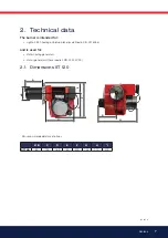
Page 7: ...il B10 heating oil biofuel blend as defined in DIN V51603 6 and is used for Water heating generators Hot air generators these require LMO 24 255 C2E 2 1 Dimensions ST 120 Min recommended distance to f...

Page 8: ...5 Flange 1 d1 d 2 d 3 Combustion device d1 d2 d3 ST 120 KA 90 M10 125 150 2 3 Burner installation 2 3 1 Hole patten Make sure the hole pattern on the boiler is designed for burner flange Length of bl...

Page 9: ...h 24 66 kW mbar Type Motor Complete burner Sound ST 120 KA 90W 0 75A 230V 50 60Hz 4 F 230V 0 8A 50Hz 70 dBA 0 5 dBA 2 5 1 Electric Specification Burner correspond to IP 20 a b c NB It is important th...

Page 10: ...0 39 3 42 40 0 85 2 83 33 3 00 36 3 16 37 3 32 39 3 47 41 3 61 43 3 74 44 3 87 46 1 00 3 33 39 3 53 42 3 72 44 3 90 46 4 08 48 4 24 50 4 40 52 4 56 54 1 10 3 66 43 3 88 46 4 09 48 4 29 51 4 48 53 4 67...

Page 11: ...tion cables 5 Nozzle assembly 6 Nozzle 7 Brake plate 8 Blast tube 9 Ignition electrodes 10 Connecting pipe 11 Air damper 12 Solenoid valve 13 Pump 14 Drive coupling 15 Indication air damper 16 Fan whe...

Page 12: ...ot pinched or otherwise damaged during installation or servicing 3 1 1 Installation and Maintenance Manual The maintenance instructions supplied with the burner must be kept at an easily accessible lo...

Page 13: ...ected to tensile stresses or become excessively bent when the burner is swung out or removed for servicing The oil filter should be installed so that the filter cartridge can easily be replaced or cle...

Page 14: ...of the oil filter 3 For single pipe systems the return plug must be removed refer to Pump instructions 4 When installing oil hoses check that the supply and return hoses are fitted to the appropriate...

Page 15: ...16 ST 120 RV 69 16 Burner output 30 kW Output calculation due to preheater for nozzle choice according to the table refer to Technical data Estimated nozzle output 30 x 1 06 31 8 kW 31 8 11 86 2 68 k...

Page 16: ...16 Bentone...

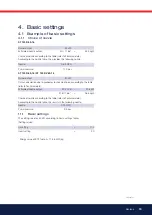
Page 17: ...position affects airflow Therefore it is always necessary to fine tune airflow using the burner s airflow regulator 4 1 3 Air intake adjustment Setting the air intake is very important to achieve goo...

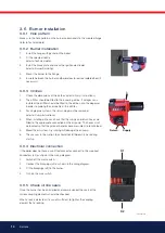
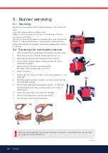
Page 18: ...off mains power and disconnect the Europlug from the burner 2 Remove the burner from the boiler by loosening the screw A 3 Loosen the housing screw B and remove the front cover C 4 Visually inspect t...

Page 19: ...pump 5 Disconnect the solenoid valve cable from the pump 6 Disconnect the connection tube D from the pump 7 Loosen the screws E and pull out the oil pump 8 Install the new oil pump on the burner Tigh...

Page 20: ...eel 9 Fit the fan wheel to the motor tighten the locking screw The fan wheel must be fitted with a little play between the motor and the fan wheel Make sure that there are no scratching noises Refit t...

Page 21: ...witch on mains power start the burner and check the combustion 5 6 Replacing the entire electrical package 1 Switch off mains power and disconnect the Europlug from the burner 2 Remove the burner from...

Page 22: ...emove the burner control and loosen the two bottom screws in the relay socket 4 The Europlug plate is firmly attached under the relay socket 5 Remove the cable of the component to be replaced 6 Connec...

Page 23: ...a new one Replace the cover tighten lightly Do not forget to replace the gasket Open the oil supply and switch on the power 5 8 3 1 One pipe system Remove the filter refer to Filter replacement BFP 11...

Page 24: ...ined by the pressure set at the regulator valve P1 and by the size of the oil nozzle in the nozzle line The valve P1 functions as follows When the oil has reached opening pressure the passage to the r...

Page 25: ...al BFP pump BFP LE S pumps cannot be converted into standard pumps and the stan dard BFP pump cannot be converted to the LE S system The LE valve must be fitted when using the LE S pump The LE valve m...

Page 26: ...s comprise theoretically calculated values where pipe dimensions and oil flow are adapted to prevent turbulent flows from occurring Turbulent flows can result in pressure losses and noise in the pipew...

Page 27: ...27 Bentone 165 105 31 6 Oil burner control 6 1 Wiring diagram Mains connection and fuses in accordance with local regulations A DC Bl Svart LMO QRB 11 12 Blue Blau Bleue Black Schwarz Noir A1...

Page 28: ...rol 3 a b The safety time expires If no flame is established before this time limit the control cuts out If for some reasons the flame disappears after this time limit the burner will make an attempt...

Page 29: ...sed the problem by pressing and holding the reset button for 3 seconds The number of flashes below is repeated with a pause in between 2 flashes No flame signal when safety time expires 4 flashes Fals...

Page 30: ...nt light Check high voltage wiring and ignition electrodes Check preheater function Symptom Burner does not start Burner pre ventilates Burner stops Causes Fuse blown Boiler thermostat has not reset P...

Page 31: ...ght Adjust the burner Check preheater function Adjust the preheater s set operating temperature Ensure that the new oil s physical parame ters are within the limits for which the burner is designed If...

Page 32: ...171 905 28...

Page 33: ...Address Test performed by Postal address Company name Tel no Boiler Type Make Power kW Bentone Burner Type Model Serial no Fuel Step 1 Step 2 Step 3 Draught in fireplace Fan Press mbar Filter smoke nu...

Page 34: ...perature If the burner will not start Press the reset button on the relay Check that the thermostats are correctly adjusted Don t forget the room thermostat check that any fusesare intact and main swi...

Page 35: ......

Page 36: ...Enertech AB P O Box 309 SE 341 26 Ljungby www bentone se www bentone com...

Reviews: