background image

110

CTC EcoLogic Pro/Family 

For the installer

9.4.7 

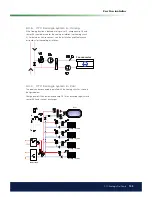
CTC EcoLogic system 6 – Solar energy

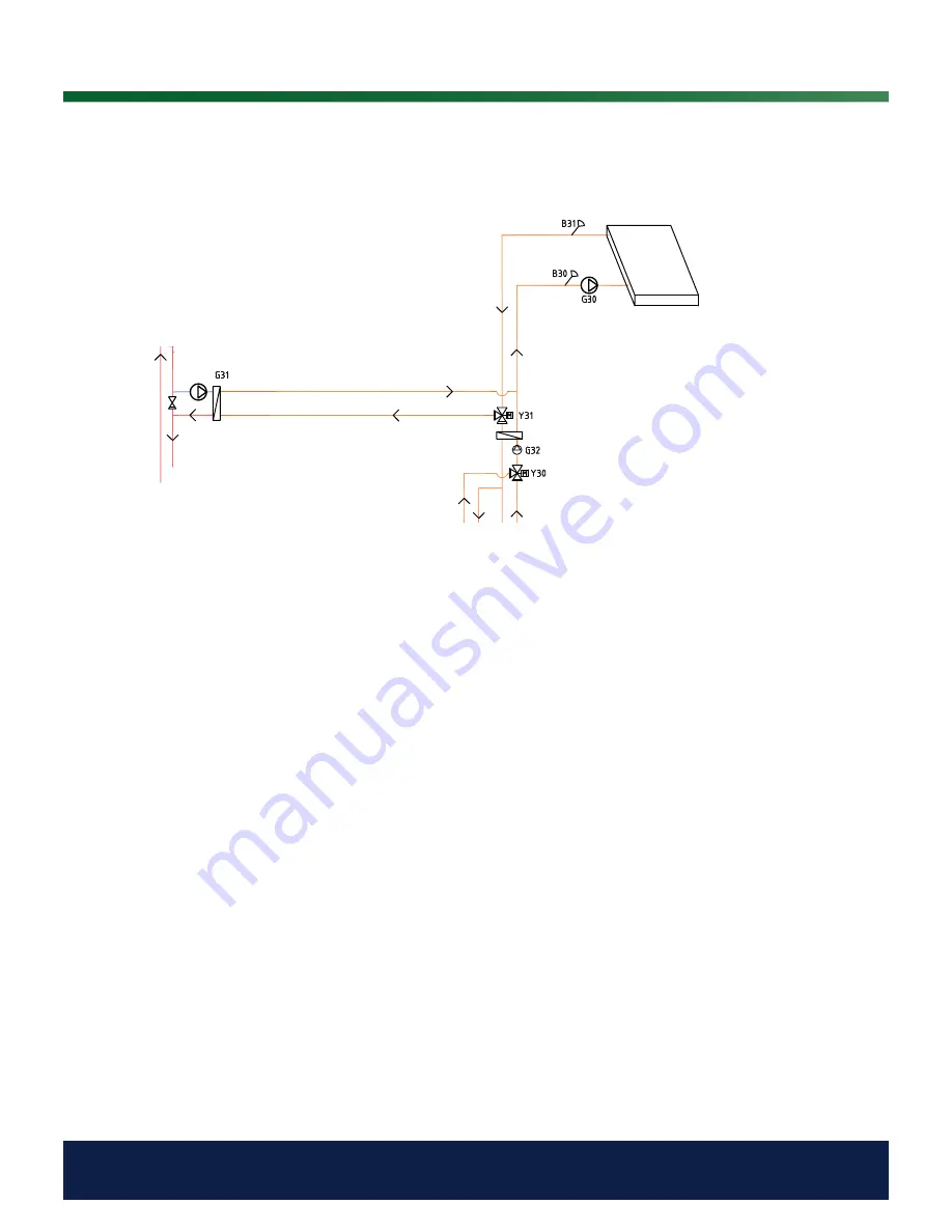
From the solar panels, the heat low is directed to the hot water tank/buffer 
tank or to the ground heating loop in order to recharge the bedrock/ground 
once the hot water tank is fully charged.

The speed-controlled pump (G30) and sensors B31 and B30 are itted next 
to the solar panels.

For recharging the bedrock/ground, a diverting valve (Y31), heat exchanger 
and charge pump (G31) are connected.

The diverting valve (Y31) is itted together with the speed-controlled pump 
(G32) and heat exchanger in order to direct the low towards the hot water 
tank or the buffer tank. Heat exchangers and pumps (G32) do not need 
to be installed to the solar heating circuit if there is already a loop in the 
connected hot water/heating tank.

When the recharging function is in operation, the CTC EcoLogic also starts 
the brine pump in the heat pump (CTC EcoPart). The charge pump for 
recharging the bore hole (G31) ensures there is suficient low through the 
heat exchanger.

Solar panels

Summary of Contents for CTC EcoLogic Family series

Page 1: ...Providing sustainable energy solutions worldwide Installation and Maintenance Manual CTC EcoLogic Pro Family 162 105 48 3 2016 04 08 IMPORTANT READ CAREFULLY BEFORE USE KEEP FOR FUTURE REFERENCE...

Page 2: ......

Page 3: ...162 105 48 3 2016 04 08 Installation and Maintenance Manual CTC EcoLogic Pro Family...

Page 4: ...______________________ 34 5 Menu overview___________________________________________________ 68 5 1 Room temp _________________________________________________ 69 5 2 DHW _____________________________...

Page 5: ...ntrol system that monitors and controls your entire heating circuit regardless of how you choose to tailor it Congratulations on buying your new product The CTC EcoLogic has a control system that moni...

Page 6: ...afety instructions must be observed when handling installing and using the product Do not soak the product with water or any other liquid All installation must be carried out by a qualiied person in a...

Page 7: ...CTC EcoLogic This chapter illustrates the main components and describes the subsystems which in different conigurations form part of the six main systems EcoLogic systems 1 to 6 For more information...

Page 8: ...igure below shows the main components in the EcoLogic delivery A Electrical connection box B Electrical connection box communication cable display unit C Display unit D Wall mounting for display unit...

Page 9: ...see the schematic diagrams for EcoLogic systems 1 to 6 in the Pipe installation chapter the control system measures the temperature in the heating circuit each minute Once a certain cumulative heat l...

Page 10: ...value obtained from the heat pump as this is a more advantageous operation for the compressor The heat pump therefore only heats to the temperature required by the heating circuit This is economical i...

Page 11: ...coAir than from the CTC EcoPart This combination is excellent in installations where for example bedrock ground source heat pumps are designed with too much focus on saving etc An air water heat pump...

Page 12: ...eat pump will vary depending on the operating conditions during the year When the outdoor temperature is less than 2 C the charge pumps must start in order to protect against frost in cases where an a...

Page 13: ...minutes For EcoLogic systems 4 5 and 6 additional heat can be set to start at a certain time after heat loss occurs in the tank The factory setting is 180 minutes 1 4 1 Wood Boiler The CTC EcoLogic i...

Page 14: ...k temperature increases or the solar panels drop in temperature and the temperature difference becomes 3 C factory setting the charging stops and does not start again until the temperature is at least...

Page 15: ...order for the charging to start see the Installer Settings Solar panels dT max bedrock C menu When the difference between the temperature in the solar panels and the brine circuit falls to 30 C the c...

Page 16: ...oling menu it is stated at which temperature cooling will be permitted 1 8 Pool For EcoLogic systems 4 to 6 the pool can be connected parallel with the heating circuit via a heat exchanger in order to...

Page 17: ...se values It is extremely important to set the heating curve and in some cases unfortunately this process may take several weeks The best way of doing this upon the initial start up is to select opera...

Page 18: ...quired Adjustment if it is too warm indoors If the outdoor temperature is lower than 0 degrees Decrease the Inclination value by a couple of degrees Wait 24 hours to see if any further adjustment is r...

Page 19: ...C Primary Flow Temperature Primary Flow Temperature Primary Flow Temperature Outside Temperature Outside Temperature Heating off out Outside Temperature Adjustment The curve can be parallel displaced...

Page 20: ...er to commence automatically at 18 C as Heating mode is set to Auto Heating mode Auto Auto On Off Auto means automatic On means that the heating is on For systems with a mixing valve and a radiator pu...

Page 21: ...2 3k 100 1 7k Hot gas sensor NTC 3 3 type C ohm 20 61 5k 30 39 5k 40 26k 50 17 5k 60 12 1k 70 8 5k 80 6 1k 90 4 5k 100 3 3k 110 2 5k 120 1 9k 130 1 5k 150 0 9k Outdoor sensor NTC 150 type C ohm 20 1...

Page 22: ...uestion is displayed here 2 Room temperature heating circuit 2 If room sensor 2 is deined the room temperature in question is displayed here Tank temperature This shows the current water temperature i...

Page 23: ...o the section of the house where a ire is burning 4 2 1 Setting without a room sensor If a room sensor has not been installed this can be selected from the Installer Deine system Heating circuit menu...

Page 24: ...the Night reduction setting Reducing a heat pump s tempera ture at night is a comfort setting which generally does not reduce energy consumption 4 2 4 Holiday The time on the left must be lower than t...

Page 25: ...ter production for certain times using the Weekly program function recommended The example above shows that Extra DHW is On for 3 5 hours 4 3 1 Weekly program DHW You can use this menu to schedule per...

Page 26: ...hot water tank is shown above this symbol 60 C Additional heat temperature The symbol represents an additional heat source E1 E2 E3 and E4 above which the current additional heat temperature 60 C is s...

Page 27: ...t temperature in the external hot water tank sensor B41 Buffer tank 39 40 This shows the temperature in the buffer tank sensor B6 and the setpoint that the system is trying to achieve Primary low C 24...

Page 28: ...ic systems 4 5 and 6 and indicates whether additional heat is connected via the mixing valve Y1 Number of heat pumps 3 Shows actual number of heat pumps in operation Degree minute 61 Shows current hea...

Page 29: ...rc pump 2 On On Off Shows the operating status of the heating circ pump G2 Mixing valve 2 Opens Opens Closes Indicates whether the mixing valve Y2 increases opens or reduces closes Once the correct te...

Page 30: ...the cooling installation if cooling has been deined Installer Deined system Coolingmenu Once the correct temperature has been reached the mixing valve s motor then shuts down Room temperature 4 C 21 9...

Page 31: ...pump s compressor is off and start ready Flow on The heat pump and fan are started before the compressor Shown for EcoAir heat pumps On heating The heat pump s compressor heats the heating circuit Def...

Page 32: ...rt heat pumps Brine in out C 4 1 99 to 99 99 to 99 This shows the brine pump s incoming and outgoing temperatures Shown for EcoPart heat pumps Fan On On Off Shows the pump s operational status Shown f...

Page 33: ...rom the solar panels sensor B31 To solar panels C 60 99 to 99 This shows the temperature of the low supplied to the solar panels sensors B30 Pump solar panel 46 0 to 100 This shows the current charge...

Page 34: ...lick on the time symbol Press OK to highlight the irst value and use the arrows to set the correct value Setting the language Click on the language symbol Select the language you want by clicking on t...

Page 35: ...pump circulates constantly Off There is no heating the radiator pump does not run is turned over Heating mode ext Switching between heating and summer mode can be controlled remotely Enter here what w...

Page 36: ...set is the outgoing low temperature to radiators when the outdoor temperature is 15 C Curve adjustment 0 20 to 20 The adjustment means that the temperature level can be raised or lowered at a speciic...

Page 37: ...coLogic systems 4 5 and 6 Alarm room temp C 5 40 40 When the room temperature is too low alarm message is sent to the CTC SMS Smart low price C 1 Off 1 5 Setting to increase curve adjustment at energy...

Page 38: ...etpoint is equal to the Floor function temp C The inal step may be less than 5 C 3 Stepped decrease After the stepped increase and 10 days at an even temperature the temperature setpoint is reduced to...

Page 39: ...the primary low is less than or equal to the setpoint minus the set value the degree minutes are set to the start value for the irst heat pump factory set to 60 Max prim low HP add heat diff C 14 5 t...

Page 40: ...rt 400 and CTC EcoAir 400 name is changed with CTC Basic Display NB Only valid for heat pump CTC EcoAir 500M Cont brine pump on No No Yes Setting for whether the brine pump is permitted to run all the...

Page 41: ...her or not EcoMiniEl E3 is connected Also specify whether the immersion heater is to connect 1 2 or 3 steps Valid for EcoLogic systems 2 3 and 4 Start EcoMiniEl degree min 500 900 to 30 This menu is u...

Page 42: ...y the outdoor temperature at which you require additional heat to be stopped blocked Boiler open mixing valve C 70 10 to 80 This menu is used to deine the temperature at which the boiler s mixing valv...

Page 43: ...heat pump charging the hot water tank Yes means that the setpoint for the additional heat is automatically set to the same as the setpoint for the heat pump of the DHW tank Demand means that the addi...

Page 44: ...ture that interrupts hot water charging If there is a heating requirement the system then diverts to charging the heating circuit Run time DHW circ 4 1 to 90 The operating time the domestic hot water...

Page 45: ...tart and stop conditions in charging the buffer tank Timer setpoint 50 20 to 60 This menu is used to specify the setpoint that is active during the period of time set by the timer Timer buffer tank Se...

Page 46: ...C 18 1 to 30 Setting for maximum permitted brine temperature Solar charging of the bore hole ceases when this value has been reached NOTE This should not be adjusted without consulting your installer...

Page 47: ...ore hole This is in order to prevent excessively high temperatures in the solar panels Applies once the maximum permitted temperature has been reached NOTE Under no circumstances are the temperatures...

Page 48: ...stop and start temperature in the pool is speciied here Pool prio C Low Low High The priority between pool heating and the heating circuit is speciied here If the Low setting is selected the pool is n...

Page 49: ...ling Cooling permit from outdoorT C From 0 to 39 From The outdoor temperature from which cooling will be permitted is determined in this menu At outdoor temperatures lower than the set value cooling i...

Page 50: ...talled Wire or wireless Wireless Wire Wireless Select whether the room sensor for the respective heating circuit is permanently connected wired or wireless 4 5 3 3 Def heat pump Heat pump A1 A10 On Of...

Page 51: ...nected Valid for EcoLogic systems 2 3 and 4 Add heat 0 10V E2 No Yes No Set if additional heat 0 10 V E2 has been connected Applies to EcoLogic systems 2 3 and 4 Heat pumps for DHW A1 A1 A1 A2 Set if...

Page 52: ...ar panels are vacuum or lat solar panels Bore hole recharge Y31 G31 No Yes No There is an option of recharging the bore hole using energy from the solar panels when the ordinary heating and domestic h...

Page 53: ...If Yes the menus below will be displayed Level of Signal The level of signal of the reception is shown here Phone Number 1 The irst activated phone number is shown here Phone Number 2 The second acti...

Page 54: ...ating from HS3 Heating from HS4 Smart A Smart B Terminal blocks inputs There are two programmable 230V inputs and two low voltage ports on the relay card A2 Open terminal block no external effect Norm...

Page 55: ...4 Smart A Smart B Example in which Heating ext mode HS1 has been assigned terminal block K24 for remote control This is done in Define Remote Control Example In the example there is manual control of...

Page 56: ...In the example with remote controlled Heating ext mode K24 is assigned A selection is then made of what is normal mode arrow 1 Normal mode was selected here as Heating mode On When this has been done...

Page 57: ...e at work Ripple control Disconnecting the compressor and immersion heater during a certain period which is deined by the electricity supplier special equipment Ripple control is a device which an ele...

Page 58: ...eating ext mode HS4 With remote controlled Heating etc mode On is selected if the heating is to be on or Off if the heating is to be switched off Auto mode can also be selected Read more in the sectio...

Page 59: ...mart A K24 Smart B K25 Example in which Smart A has been assigned low voltage input K24 and Smart B has been assigned low voltage input K25 Procedure First of all Smart A and Smart B are assigned a se...

Page 60: ...can be controlled Room temperature heating systems 1 4 Primary flow temperature heating systems 1 4 Upper tank Lower tank Pool Cooling Comment re cooling When active cooling setpoint has not been reac...

Page 61: ...ting Smart low price C EcoZenith 550 Heating System 2 is not affected Blocking mode A Closed B Open The heat pump and immersion heater can be blocked in accordance with the settings in heat pump and i...

Page 62: ...g Smart overcap C Upper tank Heat pump The heat pump only operates in the lower tank Upper tank Immersion heater Setpoint is Min temp C increase of 10 C Factory setting Smart overcap C Lower tank Heat...

Page 63: ...Test heating circuit If a number of heating circuits have been installed they will all be displayed here Mixing valve 1 4 Opens Closes Opens and closes the respective mixing valve Heating circ pump 1...

Page 64: ...n test heating cable 4 way valve Y11 Off Off On Function test 4 way valve Y11 Installed on CTC EcoAir Test Valves The following valves are function tested from this menu Diverting valve Y21 Heating DH...

Page 65: ...formation about the latest alarms from the heat pump that sounded the alarm The latest alarm is displayed at the top and the four latest alarms are shown under Stored alarms An alarm which reoccurs wi...

Page 66: ...This command re launches the installation sequence See the chapter on First start 4 5 4 8 Calibration Sensor Primary low VS 1 C B1 0 0 3 0 to 3 0 Correction of primary low sensor B1 Primary low VS 2 C...

Page 67: ...67 CTC EcoLogic Pro Family For the property owner...

Page 68: ...CTC EcoLogic Tuesday 08 45 Weekly schedule DHW Operation Installer Time Language Settings Defined system Service Night reduction Holiday Heating circuit 2 Heating circuit 1 Room temp 22 3 C 23 5 C 22...

Page 69: ...period 3 days Night reduction heat circ Weekly program Day by day Monday Tuesday Wednesday Thursday Friday Saturday Sunday Night reduction heat circ Weekly program Block Decrease Sunday 22 00 Increase...

Page 70: ...owner 5 2 DHW 06 09 18 21 07 09 20 23 06 09 06 21 06 21 10 12 20 23 10 12 20 23 Weekly program DHW DHW Extra DHW 0 0 hours On Temperature Normal Weekly schedule Weekly program Day by day Monday Tuesda...

Page 71: ...Room temp 3 C 21 8 22 Primary flow 3 C 37 38 Radiator pump 3 Off Mixing valve 3 Close Room temp 4 C 21 9 23 Primary flow 4 C 39 40 Radiator pump 4 Off Mixing valve 4 Close Operation data heating Opera...

Page 72: ...Heating circuit 1 Heat pump 1 Compressor Permitted Stop at outdoor temp C 22 Start at degree minute 60 Max primary HP diff C 10 Max primary HP Add diff C 14 Diff between HP 60 Delay between HP 30 Pri...

Page 73: ...time DHW circ 4 Cyclic time DHW circ 15 Diff start ext DHW tank 5 Timer DHW circ Timer DHW circulation Monday Tuesday Wednesday Thursday Friday Saturday Sunday Solar panels dT max solar C 7 dT min so...

Page 74: ...Heat pump 9 Off Heat pump 10 Off Flow level switch None Def system type System type 2 Add heat E1 Yes EcoMiniEl E3 No Add heat 0 10V E2 No Heat pumps for DHW A1 Heating flow during DHW G1 No Def DHW...

Page 75: ...ing valve2 Off Rad pump2 Off Mixing valve3 Off Rad pump3 Off Mixing valve4 Off Rad pump4 Off LED room sensor On Test valves Diverting valve Y21 DHW Diverting valve Y22 Heating Test Additional heat Rel...

Page 76: ...k vs primary C Start stop diff tank C DHW tank Factory setting User value Stop temp HP C Start stop diff C Extra DHW stop temp C Max time DHW Max time heating Delay heating calc Add heat DHW Demand Ad...

Page 77: ...Def heating circuit 3 Radiator system 3 Y3 G3 Room sensor 3 B13 Wire or wireless Def heating circuit 4 Radiator system 4 Y4 G4 Room sensor 4 B14 Wire or wireless Cooling Cooling permit from outdoorT O...

Page 78: ...en using an ire place or open stove The alarm LED on the room sensor still functions as normal If you use the ire or open stove only occasionally the iring process can affect the room sensor and reduc...

Page 79: ...t radiator thermostats should always be fully open in the area where the room sensor is located A correctly operating heating circuit is of signiicant importance to the heat pump s operation and affec...

Page 80: ...the brine system Check that the brine pump speed value is not set too low Try to increase this if a problem arises Reset the Low evaporation alarm on the display Where a malfunction repeatedly occurs...

Page 81: ...ripple control is active Tariff HP off This is used when a dual tariff is used with lower energy costs at set hours of the day The heat pump can then take advantage of reduced primary energy costs Ta...

Page 82: ...isplayed if a fault occurs with a sensor that is not connected or has short circuited If this sensor is signiicant to the system s operation the compressor stops In this case the alarm is reset manual...

Page 83: ...the fault recurs contact your installer High evaporation This message appears when the evaporation temperature is high Press reset and check whether the alarm recurs If the fault recurs contact your...

Page 84: ...nnecting the heating circuit to an existing boiler using a mixing valve The control system starts the boiler only as required as the mixing valve mixes in the additional heat The hot water is preheate...

Page 85: ...the outer wall of the house protected from direct sunlight It is connected using a 2 conductor cable min 0 5 mm The room sensors B11 to B14 must be itted in an open space in the property where a repre...

Page 86: ...he Installation and Maintenance instructions of the respective heat pump 9 1 3 CTC EcoLogic system 1 Hot water The hot water is preheated in the boiler by the heat pump and then heated up in a separat...

Page 87: ...temperature and signals to the control system that wood is being lit The sensor B9 should be itted so that the boiler temperature is measured 9 1 5 CTC EcoLogic system 1 Cooling If the Cooling functi...

Page 88: ...re itted next to the solar panels For recharging the bedrock ground a diverting valve Y31 heat exchanger charge pump G31 and non return valve are connected When the recharging function is in operation...

Page 89: ...nnect the tank to the system not to heating circuit 4 Solar energy can be connected either to the hot water tank or to the buffer tank using diverting valves The solar energy can also be used to recha...

Page 90: ...ps A1 and A2 can be connected using diverting valves that direct the low either to the hot water system or the heating circuit The other heat pumps are connected to the heating circuit Solar energy ca...

Page 91: ...ating circuit 2 The outdoor sensor B15 must be itted to the outer wall of the house protected from direct sunlight It is connected using a 2 conductor cable min 0 5 mm The room sensors B11 to B14 must...

Page 92: ...G13 to G20 are controlled from their respective heat pumps Heat pumps A1 and A2 can be connected using diverting valves that direct the low either to the hot water system or the heating circuit If mo...

Page 93: ...g valve and chilled water released down into the tank before once more being heated up The non return valves are necessary to ensure that circulation proceeds as intended Control valves allow the desi...

Page 94: ...E1 is connected the mixing valve Y2 is used to connect the add heat to the system not to heating circuit 2 If the buffer tank is connected the mixing valve Y4 is used to connect the tank to the syste...

Page 95: ...30 and sensors B31 and B30 are itted next to the solar panels For recharging the bedrock ground a diverting valve Y31 heat exchanger and charge pump G31 are connected The diverting valve Y31 is itted...

Page 96: ...the heat low either to the hot water system or to the heating circuit The other heat pumps are connected to the heating circuit Solar energy can be connected either to the hot water tank or to a buffe...

Page 97: ...can be connected using diverting valves that direct the low either to the hot water system or the heating circuit The other heat pumps are connected to the heating circuit Solar energy can be connect...

Page 98: ...heating circuit 2 The outdoor sensor B15 must be itted to the outer wall of the house protected from direct sunlight It is connected using a 2 conductor cable min 0 5 mm The room sensors B11 to B14 m...

Page 99: ...cted using diverting valves that direct the low either to the hot water system or the heating circuit If more heat pumps are installed these should be connected to the heating circuit Be careful to en...

Page 100: ...by the mixing valve and chilled water released down into the tank before once more being heated up The non return valves are necessary to ensure that circulation proceeds as intended Control valves a...

Page 101: ...own in the igure When additional heat E1 is connected the mixing valve Y2 is used to connect the add heat to the system not to heating circuit 2 Sensor B10 should be connected to measure the temperatu...

Page 102: ...cooling installation not heating circuit 3 For details on how to connect see the Installation and Maintenance instructions for the cooling installation Pool Buffer tank Fan convector 9 3 6 CTC EcoLog...

Page 103: ...valve Y31 heat exchanger and charge pump G31 are connected The diverting valve Y31 is itted together with the speed controlled pump G32 and heat exchanger in order to direct the low towards the hot w...

Page 104: ...energy can be connected either to the hot water tank or to a buffer tank using diverting valves or to a ground heating loop Cooling can easily be connected to the bedrock ground source heating system...

Page 105: ...e protected from direct sunlight It is connected using a 2 conductor cable min 0 5 mm The room sensors B11 to B14 must be itted in an open space in the property where a representative temperature is e...

Page 106: ...ective heat pumps Heat pumps A1 and A2 can be connected using diverting valves that direct the low either to the hot water system or the heating circuit If more heat pumps are installed these should b...

Page 107: ...to the tank before once more being heated up The non return valves are necessary to ensure that circulation proceeds as intended Control valves allow the desired low of the circuit to be adjusted Opti...

Page 108: ...er 9 4 4 CTC EcoLogic system 6 Additional heat Additional heat E1 is connected to the hot water tank and connected to the heating circuit in parallel with the buffer tank using a 4 way bivalent mixing...

Page 109: ...with sensor B50 and the heat exchanger 9 4 6 CTC EcoLogic system 6 Cooling If the Cooling function is deined mixing valve Y3 charge pump G3 and sensor B3 should be used for the cooling installation n...

Page 110: ...ve Y31 heat exchanger and charge pump G31 are connected The diverting valve Y31 is itted together with the speed controlled pump G32 and heat exchanger in order to direct the low towards the hot water...

Page 111: ...ng valve 1 Open pole A27 Close pole A28 Zero pole A29 Y2 Mixing valve 2 Open pole A15 Close pole A16 Zero pole A17 Y3 Mixing valve 3 expansion card X6 Open pole 12 Close pole 13 Zero pole 14 Y4 Mixing...

Page 112: ...the motor counterclockwise CCW The motor is itted to the diverting valve by a screw To unfasten the motor remove the knob by pulling it off unfasten the screw and remove the motor To prevent faults tu...

Page 113: ...ler Service Function test in the control system 10 2 3 Charge pumps VPA1 VPA2 G11 G12 230V 1N Charge pumps G11 and G12 can be controlled from CTC EcoLogic while the system s other charge pumps G13 to...

Page 114: ...iniEl E3 must have a common connection to the neutral block E4 Add heat DHW Relay output A8 pole A13 10 2 5 Circulation Pump hot water G40 230 V 1N The circulation pump is connected to the following t...

Page 115: ...e function by test running the pump in menu Installer Service Function test in the control system 10 2 8 Diverting valve solar DHW Y30 230 V 1N The diverting valve is connected to the following termin...

Page 116: ...50 and G51 expansion card X7 Phase pole 33 Zero pole 35 Earth pole 34 Pole 33 is connected to an external connection box which distributes voltage to the charge pump G50 and circulation pump G51 Check...

Page 117: ...thwestern direction The sensor should be placed out of direct sunlight However where this is dificult to achieve it can also be shielded from the sun by a screen Remember that the sun rises and sets a...

Page 118: ...er Position in asensor pipe or on the jacket surface in the hot water tank The sensor is connected to the PCB in positions G63 and G64 B41 Sensor external DHW tank Position in a sensor pipe or on the...

Page 119: ...and connection 3 Select Off If the LED goes off the check is complete Check connected sensors If any sensor is incorrectly connected a message will appear on the display e g Alarm sensor out If severa...

Page 120: ...120 CTC EcoLogic Pro Family For the installer 11 Wiring diagram...

Page 121: ...121 CTC EcoLogic Pro Family For the installer...

Page 122: ...culation pump solar panels G31 Charge pump recharging bore hole G32 Pump heat exchanger solar panels G40 Circulation pump hot water G41 Charge pump External DHW tank G50 Pump pool G51 Pump pool Y1 Mix...

Page 123: ...anels Out PT 1000 B41 Sensor external DHW tank NTC 22 B50 Sensor pool NTC 22 HP A1 Heat pump A1 HP A2 Heat pump A2 HP A3 Heat pump A3 HP A4 Heat pump A4 HP A5 Heat pump A5 HP A6 Heat pump A6 HP A7 Hea...

Page 124: ...nce 300 64 130 800 70 32 290 74 125 906 65 37 280 85 120 1027 60 43 270 98 115 1167 55 51 260 113 110 1330 50 60 250 132 105 1522 45 72 240 168 100 1746 40 85 230 183 95 2010 35 102 220 217 90 2320 30...

Page 125: ...he menu Installer Settings Save set tings If heating circuits 3 and 4 are to be used they are activated in the menu Installer Define system Heat ing circuit 3 4 First start Switch on the power using t...

Page 126: ...es exigences des normes suivantes to which this declaration relates is in conformity with requirements of the following directive auf das sich diese Erkl rung bezieht konform ist mit den Anforderungen...

Page 127: ......
Page 128: ...Enertech AB P O Box 309 SE 341 26 Ljungby Sweden www ctc se www ctc heating com 162 105 48 3 2016 04 08...

Reviews: