165
Installation instructions for professionals
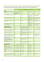
Location on MD
controller card
Voltage/current
Cable example
External wiring of
the ventilation unit
TE10 supply air temperature
(Dehum/Twin Tropic/TCG)
AI12
(program-defined)
0–10 VDC
KLM 4x0.8
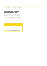
Yes, if duct coil
Free
AI13
(program-defined)
0–10 VDC
KLM 4x0.8
Free
AI14
(program-defined)
0–10 VDC
KLM 4x0.8
Free
AI15
(program-defined)
0–10 VDC
KLM 4x0.8
Free
AI16
(program-defined)
0–10 VDC
KLM 4x0.8
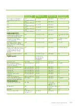
Analog outputs (AO)
Cooling control voltage /
additional post-heating control
voltage (MDX-E/HP-E/HP-W)
AO3
0-10 VDC 10 mA
KLM 2x0.8
Yes, except if in-built
coil
Heating control voltage /
compressor power control
voltage (MDX/HP)
AO5
0-10 VDC 10 mA
KLM 2x0.8
Yes, if MDX or water
heating
Pre-heating control voltage /
pre-cooling control voltage
(CHG) / LTO n:o 2 control voltage
(Twin Tropic)
AO6
0-10 VDC 10 mA
KLM 2x0.8
Yes, CHG
Exhaust air pre-heating control
voltage (HP) / exhaust air drying
control voltage (TCG) / LTO
de-frosting control voltage
(WGHR)
AO7
0-10 VDC 10 mA
KLM 2x0.8
Yes, if duct heating
Hot water production control
voltage
AO8
0-10 VDC 10 mA
KLM 2x0.8
Yes
Digital inputs DI
Connected to
a potential-free
terminating
connector
Emergency stop
DI1 (fixed)
24 VDC
KLM 2x0.8
Yes
PDS10 supply air blower
pressure switch / de-frosting
indication (MDX/HP)
DI2 (user-defined)
24 VDC
KLM 2x0.8
Yes, MDX
Overtime (only in Office use)
DI3 (user-defined)
24 VDC
KLM 2x0.8
Yes
Manual boost
DI4 (user-defined)
24 VDC
KLM 2x0.8
Yes
Away mode
DI5 (user-defined)
24 VDC
KLM 2x0.8
Yes
Overpressure
DI6 (user-defined)
24 VDC
KLM 2x0.8
Yes
Central vacuum system
indication
DI7 (user-defined)
24 VDC
KLM 2x0.8
Yes
Cooker hood indication
DI8 (user-defined)
24 VDC
KLM 2x0.8
Yes
Electrical post-heating alarm /
compressor failure (MDX/HP)
DI10 (fixed)
24 VDC
KLM 2x0.8
Yes, if MDX
Other connections
Control panel connections
X27, X28
10 m cable
supplied with
the unit
Yes
Modbus-RTU
X26
Instrument cable
2x2x0,5
Yes
Ethernet
X19
Cat5
Yes
O3 ozone sensor (ION)
ICEA2000A unit
connector 11
0–10 VDC
KLM 4x0.8
Yes
Summary of Contents for LTR-3 eAir
Page 8: ...8 Kanavaliitännät ulkoilma tuloilma poistoilma jäteilma ...
Page 20: ...20 11 13 9 12 Lisävaruste 1 2 min 10 ...
Page 48: ...48 ...
Page 51: ...51 Ammattilaisen asennusohje ...
Page 52: ...52 LTR 3 eAir Installationsanvisningar för ventilationsaggregat Svenska ...
Page 58: ...58 Kanalanslutningar uteluft tilluft frånluft avluft ...
Page 70: ...70 9 13 15 11 10 14 Extra tillbehör 1 2 min 12 ...
Page 98: ...98 ...
Page 101: ...101 Installationsanvisningar för yrkesfolk ...
Page 102: ...102 Installeringsinstruksjoner for ventilasjonsenheten Norsk LTR 3 eAir ...
Page 108: ...108 Kanalkoblinger utendørsluft tilluft avtrekksluft avkastluft ...
Page 120: ...120 9 13 15 11 10 14 1 2 min 12 ...
Page 148: ...148 ...
Page 151: ...151 Installasjonsinstrukser for fagfolk ...
Page 152: ...152 LTR 3 eAir Installation instructions for the ventilation unit English ...
Page 158: ...158 Duct connections outdoor air supply air extract air exhaust air ...
Page 170: ...170 9 13 15 11 10 14 Extra 1 2 min 12 ...
Page 198: ...198 ...
Page 203: ...203 Koblinger Connections ...
Page 204: ...204 ...
Page 205: ...205 ...
Page 206: ...206 ...
Page 207: ...207 ...
Page 208: ...208 ...
Page 209: ...209 ...
Page 210: ...210 ...
Page 211: ...211 ...
Page 212: ...212 ...
Page 214: ...214 eAir W Periaatekaavio eAir W Principschema eAir W Prinsippskisse eAir W Principle schema ...
Page 215: ...215 ...
Page 218: ...218 ...
Page 219: ...219 ...


