172
Installing model eAir W
Principal, control and wiring diagrams for each model can
be found at the end of this manual.
Check the principal charts for units with fluid coil. Install and
connect the water pipes according to these charts.
Installing:
1. Install the dampers and damper motors.
2. Install and connect the water pipes.
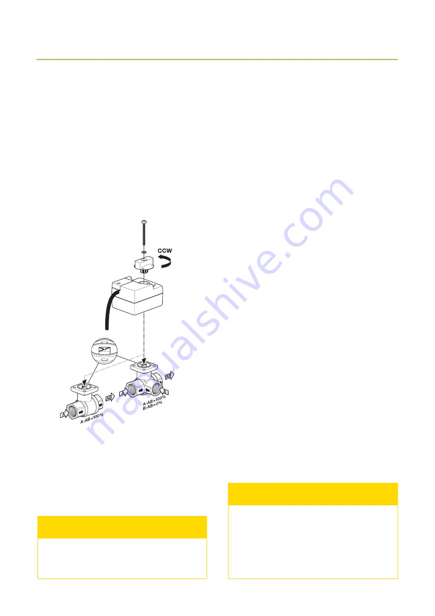
3. Install the valve and the valve actuator.
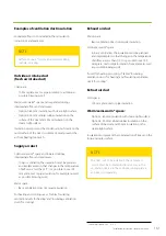
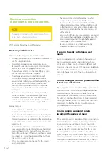
Valve and actuator open counter-clockwise and close
clockwise. Picture shows valve and actuator in the fully
open position. Also shown is the allowed direction of the
liquid flow.
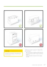
Do not install the actuator so that the manual
control knob faces downwards.
NOTE
4. Connect the water.
•
Do not connect where the water circulation stops,
eg when hot water is produced.
5. Check the water coil and its connections for leaks
immediately after the system has been filled with
water.
•
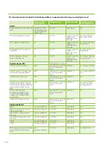
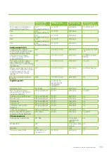
The water heating coil needs a steady flow of suf-
ficiently warm water without large temperature
fluctuations. Be sure to check and adjust the water
flow in the heating coil according to the technical
features table at the end of this manual.
•
Do not connect to a point where the water cir-
culation ends for example during hot water pro-
duction. If the water is taken for instance from a
ground source heat pump, the heating coil needs
its own circulation pump.
•
If the installation is done in wintertime it is recom-
mended not to let water in the coil until the ven-
tilation is running. This in order to prevent cold air
from entering the ventilation system and possibly
freezing the coil.
6. Connect the external cables such as the cable bet-
ween the unit and the control panel holder, external
sensor(s), actuator and pump.
•
Do not connect Modbus until all installation and
commissioning work is done.
7. Install over voltage protection to the unit.
8. Open the unit’s maintenance hatch and make sure that
•
the unit is clean from the inside
•
there are no unwanted objects inside
•
the filters are in place and
•
the condensate drain works.
9. Close the hatch carefully.
10. Connect the unit to an appropriate electric supply.
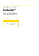
The valve and actuator must be in the same
position when connected. When the valve is in
open position, the actuator is turned counter-
clockwise before connecting, and when the
valve is closed, the actuator is turned cw before
connecting.
NOTE
Summary of Contents for LTR-3 eAir
Page 8: ...8 Kanavaliitännät ulkoilma tuloilma poistoilma jäteilma ...
Page 20: ...20 11 13 9 12 Lisävaruste 1 2 min 10 ...
Page 48: ...48 ...
Page 51: ...51 Ammattilaisen asennusohje ...
Page 52: ...52 LTR 3 eAir Installationsanvisningar för ventilationsaggregat Svenska ...
Page 58: ...58 Kanalanslutningar uteluft tilluft frånluft avluft ...
Page 70: ...70 9 13 15 11 10 14 Extra tillbehör 1 2 min 12 ...
Page 98: ...98 ...
Page 101: ...101 Installationsanvisningar för yrkesfolk ...
Page 102: ...102 Installeringsinstruksjoner for ventilasjonsenheten Norsk LTR 3 eAir ...
Page 108: ...108 Kanalkoblinger utendørsluft tilluft avtrekksluft avkastluft ...
Page 120: ...120 9 13 15 11 10 14 1 2 min 12 ...
Page 148: ...148 ...
Page 151: ...151 Installasjonsinstrukser for fagfolk ...
Page 152: ...152 LTR 3 eAir Installation instructions for the ventilation unit English ...
Page 158: ...158 Duct connections outdoor air supply air extract air exhaust air ...
Page 170: ...170 9 13 15 11 10 14 Extra 1 2 min 12 ...
Page 198: ...198 ...
Page 203: ...203 Koblinger Connections ...
Page 204: ...204 ...
Page 205: ...205 ...
Page 206: ...206 ...
Page 207: ...207 ...
Page 208: ...208 ...
Page 209: ...209 ...
Page 210: ...210 ...
Page 211: ...211 ...
Page 212: ...212 ...
Page 214: ...214 eAir W Periaatekaavio eAir W Principschema eAir W Prinsippskisse eAir W Principle schema ...
Page 215: ...215 ...
Page 218: ...218 ...
Page 219: ...219 ...

