171
Installation instructions for professionals
The ventilation unit can be controlled via Modbus as well.
There are two alternative Modbus connection methods
available. By using the X26 connector of the Modbus
RTU eAir motherboard. Or by using the Modbus TCP/IP
(md-sw version 1.30 onwards) with a X19 connector. The
connection method is selected in the settings wizard in
the eAir control panel, on the Modbus tab (eAir control
panel software version 2.07 onwards).
Modbus RTU default values
•
Modbus address 1 (1–100)
•
Communication form RS 485
•
Speed 19,200 (9,600 or 115,200) bps
•
Parity None (Even).
Modbus RTU X26 connection termination
RS485 X26 connector has options termination and
biasing. These are selected in the short-circuit block JP5,
which is right behind the X26 connection.
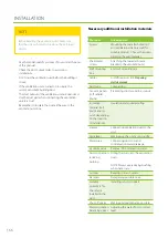
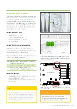
The below table shows the JP5 jumper. The bottom row is
closest to the X26 RS485 connector.
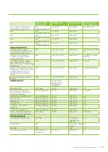
In the picture below you can see the placements of the
Modbus RTU and Ethernet / Modbus TCP/IP connections
on the eAir motherboard.
Modbus registers can be found on the Enervent website at
www.enervent.fi.
Installation to a Modbus
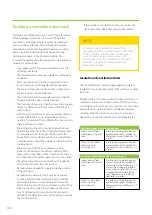
The Modbus TCP/IP connection method does not
allow any kind of authentication or encryption. The
unit must not be connected to a network that has
open access to public internet. At the minimum,
there must be a firewall that prevents external
incoming network traffic.
NOTE
[o o]
Biasing: Jumper installed = RS485 B line earthed
via the GND 600 Ω resistor.
[o o]
Termination: Jumper installed = bus terminated
[o o]
Biasing: Jumper installed = RS485 A line
connected via the +5V 600 Ω pull-up resistor
Modbus TCP/IP usage
•
Modbus address is not in Modbus TCP/IP use. Access
to unit is via the unit IP address.
•
Maximum two TCP/IP connections can be active at
the same time.
X1
X2
X3
X4
X5
X7
X12
X19
DO6
DO5
DO4
DO3
DO1
DO2
X28
X27
X26
JP5
JP2
eAir EMOKORTTI
Ha
Mu
Ru
TULO
X9
X10
DI11
GND
A01
Ethernet
MODBUS-RTU
1
2
3
4
X6
DO8
DO7
AO
8
A
B
GND
+12V
MODBUS-TCP/IP
Bus control must not be connected to the
ventilation unit before the bus is configured and
compatible with unit control parameters.
WARNING
X26
Summary of Contents for Pelican eAir
Page 8: ...8 Kanavaliitännät ulkoilma poistoilma jäteilma tuloilma ...
Page 20: ...20 13 15 11 14 Lisävaruste 1 2 min 12 9 10 ...
Page 49: ...49 Ammattilaisen asennusohje ...
Page 52: ...52 Pelican eAir Installationsanvisningar för ventilationsaggregat Svenska ...
Page 58: ...58 Kanalanslutningar uteluft frånluft avluft tilluft ...
Page 70: ...70 13 15 11 14 Extra tillbehör 1 2 min 12 9 10 ...
Page 99: ...99 Installationsanvisningar för yrkesfolk ...
Page 102: ...102 Installeringsinstruksjoner for ventilasjonsenheten Norsk Pelican eAir ...
Page 108: ...108 Kanalanslutningar uteluft avtrekksluft avkastluft tilluft ...
Page 120: ...120 13 15 11 14 Ekstrautstyr 1 2 min 12 9 10 ...
Page 149: ...149 Installasjonsinstrukser for fagfolk ...
Page 152: ...152 Pelican eAir Installation instructions for the ventilation unit English ...
Page 158: ...158 Duct connections outdoor air extract air exhaust air supply air ...
Page 170: ...170 13 15 11 14 Extra 1 2 min 12 9 10 ...
Page 199: ...199 Installation instructions for professionals ...
Page 205: ...205 ...
Page 206: ...206 Enervent Zehnder Oy Kipinätie 1 FI 06150 PORVOO Tel 358 207 528 800 enervent enervent com ...
Page 207: ...207 ...
Page 211: ...211 Enervent Zehnder Oy Kipinätie 1 FI 06150 PORVOO Tel 358 207 528 800 enervent enervent com ...
Page 220: ...220 eAir CG liitännät eAir CG anslutningar eAir CG koblinger eAir CG connections ...
Page 223: ...223 ...

