180
COMMISSIONING
Requirements
Functioning requirements of the ventilation unit:
•
Intake and exhaust air temperature less than +55°C.
•
Exhaust air temperature at least +8°C
•
Heat recovery intake air temperature over +5°C.
•
Supply air temperature over +10°C.
•
All foreign objects have been removed from the
ventilation system.
•
Both blowers are rotating.
Adjusting air flow
In order to get the optimal control values, the air flows
must be measured in each duct-opening. A suitable
instrument is a thermal anemometer or a differential
pressure instrument With the help measurements, the
air flow can be adjusted to follow the planned values.
Correctly configured ventilation unit is silent and has
good heat economy. Additionally, it maintains a minor
underpressure in the house. Underpressure prevents
humidity from getting inside the walls and ceiling.
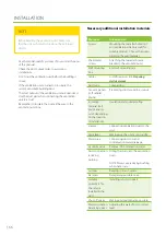
Action
Reviewed
Notes
The unit is installed according to the installation instructions
provided by the manufacturer.
Condensation water drainage pipe is attached to the water seal
and its functionality has been tested.
Dampeners have been installed in the supply air and exhaust air
ducts.
The terminals are connected to the ductwork.
Outdoor louvre has been installed for fresh air intake.
NOTE
Do not cover the louvre with mosquito netting. It makes
cleaning difficult.
The unit is connected to the appropriate electric input.
Ventilation ducts are insulated according to the ventilation plan.
Condensation water drainage is attached to the water seal and its
functionality has been tested.
Commissioning check list
Do not cover the outdoor louvre with
mosquito netting.
FOR INFORMATION
When the unit has been started, the air flows must be
configured to the designed values.
•
Air flows are adjusted when commissioning the
ventilation unit.
•
The controls are done separately for both blowers in
each mode (= blower speed).
Check the following when setting up:
•
All filters are clean.
•
All supply and exhaust air valves, the feedthrough in
the ceiling, and the outdoor louvre are in place.
Summary of Contents for Pelican eAir
Page 8: ...8 Kanavaliitännät ulkoilma poistoilma jäteilma tuloilma ...
Page 20: ...20 13 15 11 14 Lisävaruste 1 2 min 12 9 10 ...
Page 49: ...49 Ammattilaisen asennusohje ...
Page 52: ...52 Pelican eAir Installationsanvisningar för ventilationsaggregat Svenska ...
Page 58: ...58 Kanalanslutningar uteluft frånluft avluft tilluft ...
Page 70: ...70 13 15 11 14 Extra tillbehör 1 2 min 12 9 10 ...
Page 99: ...99 Installationsanvisningar för yrkesfolk ...
Page 102: ...102 Installeringsinstruksjoner for ventilasjonsenheten Norsk Pelican eAir ...
Page 108: ...108 Kanalanslutningar uteluft avtrekksluft avkastluft tilluft ...
Page 120: ...120 13 15 11 14 Ekstrautstyr 1 2 min 12 9 10 ...
Page 149: ...149 Installasjonsinstrukser for fagfolk ...
Page 152: ...152 Pelican eAir Installation instructions for the ventilation unit English ...
Page 158: ...158 Duct connections outdoor air extract air exhaust air supply air ...
Page 170: ...170 13 15 11 14 Extra 1 2 min 12 9 10 ...
Page 199: ...199 Installation instructions for professionals ...
Page 205: ...205 ...
Page 206: ...206 Enervent Zehnder Oy Kipinätie 1 FI 06150 PORVOO Tel 358 207 528 800 enervent enervent com ...
Page 207: ...207 ...
Page 211: ...211 Enervent Zehnder Oy Kipinätie 1 FI 06150 PORVOO Tel 358 207 528 800 enervent enervent com ...
Page 220: ...220 eAir CG liitännät eAir CG anslutningar eAir CG koblinger eAir CG connections ...
Page 223: ...223 ...


