background image

12

010.1220.0719  01.21

4.  ELECTRICAL INSTALLATION

4.1 General

All wiring must be in compliance with the local codes or in 

their absence, with the National Electric Code, NFPA70. 

All wiring should meet these requirements: installed in rigid 

metal conduit, intermediate metal conduit, rigid non-metallic 

conduit, electrical metallic tubing, or be otherwise suitably 

protected from physical damage. All BEFx units are equipped 

with an EC-motor and operate at different voltages so it’s 
important to pay attention to the wiring details. 

Note:   If any of the original wire supplied with the system 

must be replaced, use similar wire of the same temperature 

rating. Otherwise, insulation may melt or degrade, exposing 
bare wire.

WARNING

This product is equipped with an electronically 

commutated (EC-motor) and can not be 

connected directly to ac mains. Motor must 

be connected to approved motor controller to 

ensure proper function. Failure to use approved 

motor controller may result in damage to the motor.

AVERTISSEMENT

Ce produit est équipé d’un commutateur électronique 

(moteur EC) et ne peut pas être connecté directement au 

secteur. Le moteur doit être connecté au contrôleur de 

moteur approuvé pour assurer un fonctionnement correct. 

Ne pas utiliser le contrôleur de moteur approuvé peut 

endommager le moteur.

!

WARNING

All BEF models must be operated with the 

approved factory-programmed motor drive.
DO NOT CONNECT DIRECTLY TO LINE 

VOLTAGE!

AVERTISSEMENT

Tous les modèles BEF doivent être utilisés avec 

l’entraînement motorisé approuvé en usine.
NE PAS CONNECTER DIRECTEMENT À LA TENSION DE 

LIGNE!

!

DANGER

Turn off electrical power before servicing. 

Contact with live electric components can 

cause shock or death.

DANGER

Éteignez l’alimentation électrique avant de procéder à 

l’entretien. Le contact avec des composants électriques 

sous tension peut provoquer un choc ou la mort.

ABOUT SHAFT GROUNDING

Bearing currents are very common problem of Variable 

Frequency Drives (VFD/Motor Controller) and electronic 

commutated motors. The electric-discharge machining 

(EDM) bearing currents are generated in motors because 

of unbalanced modulated voltage from drive to the motor. 

Because of stray capacitances in motor, bearing currents 

are generated in rotor and there is usually no other way to 

discharge except through bearings. This drastically lowers 

the life time of the bearings.
The BEFx’s EC-motor integrates an insulated rotor system, 

which means that electrical insulation is inserted between 

rotor and motor shaft. This system provide up to 80% 

lower shaft voltages and very low bearing current values 

which eliminates bearing damage.

DANGER

The motor speed drive is suitable for use in a 

circuit capable of receiving not more than 100 

KA RMS symmetrical Amperes at the maximum 

reated voltage.

DANGER

Le variateur de vitesse peut être utilisé dans un circuit 

capable de recevoir des ampères symétriques de plus de 

100 KA à la tension maximale.

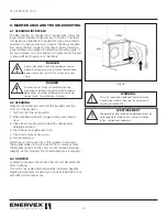
4.2 Motor Controller

All ENERVEX BEFx fans come with, and must use, a factory 

programmed EDrive motor controller with an enclosure rated 

to NEMA 4X/IP66 for indoor and outdoor installation. 
The EDrive E3 motor controller must be mounted within 300 

feet of the BEFx Fan. This distance can be increased up to 

600 feet with the addition of a line filter (Contact ENERVEX 

for details).  
A motor disconnect switch must be installed between the 

motor controller and the BEFx Fan, either within sight of the 

BEFx Fan, or within 50 feet of the BEFx Fan.  

Do not activate the motor service disconnect switch 

while the BEFx motor is running - damage could occur to 

the motor controller.
For more information about the EDrive E3, please refer to 

the Installation & Operating Manual.

Summary of Contents for BEF 225x

Page 1: ...com www enervex com 010 1220 0719 01 21 Installation Operating Manual ENERVEX BEF 225 800X BOX VENTILATOR MAKE UP AIR FOR LAUNDRY ROOMS TYPE I II RESIDENTIAL COMMERCIAL CLOTHES DRYERS KITCHEN HOOD BA...

Page 2: ...es are not covered by this manual Please refer to these component s individual manuals TO REDUCE THE RISK OF FIRE ELECTRICAL SHOCK OR INJURY TO PERSONS OBSERVE THE FOLLOWING 1 Use this unit in the man...

Page 3: ...15 4 11 Installing a Proven Flow System 16 5 STARTUP AND CONFIGURATION 5 1 Managing the Keypad 17 5 2 Operating the Display 17 5 3 Changing Parameters 18 5 4 Read Only Parameter Access 18 5 5 Resettin...

Page 4: ...mpeller is welded aluminum The design is Type B Spark Resistant Construction completely insulated against fire noise condensation and heat with 2 fiberglass insulation A service door is provided to al...

Page 5: ...ven Draft Switch PDS 1 6 Listings UL705 Standard for Power Ventilators with special consideration for venting lint laden air from single or multiple dryers and CSA 22 2 No 113 Standard for Fans and Ve...

Page 6: ...x480V 22 0 kW 51 9 A 46 0 A 51 26 1302 61 69 1567 24 09 612 20 83 529 35 83 910 41 77 1061 25 63 651 1 97 50 652 lbs 296 kg BEF 710x 3x480V 1750 RPM 70 0 Nm 321 2220 4200 3x480V 15 0 kW 34 2 A 30 0 A...

Page 7: ...stalled indoors and outdoors without any modifications Wherever the ventilor is installed make sure there is space enough to open the access door to an angle of approximately 90 as shown in Fig 4 and...

Page 8: ...entilator orientations are shown in Fig 3 The BEFx can be installed indoors and outdoors without any modifications Wherever the ventilor is installed make sure there is space enough to be able to open...

Page 9: ...p ventilator unit on pallet For the standard position Fig 5 bolt holes are pre drilled and support legs should be aligned and secured with the enclosed hardware For all other positions the legs should...

Page 10: ...s in the duct system If used the FLF should be connected between the fan inlet outlet and the main duct as shown in Fig 8 This will decrease system vibration and prevent fan housing deflection NOTE Th...

Page 11: ...attached to the motor via a flexible conduit After mounting the BEFx in its proper location and orientation the Field Junction Box MUST be permanantly attached to the fan housing with the supplied she...

Page 12: ...e proc der l entretien Le contact avec des composants lectriques sous tension peut provoquer un choc ou la mort ABOUT SHAFT GROUNDING Bearing currents are very common problem of Variable Frequency Dri...

Page 13: ...h and type the effective switching frequency the earth connections used and the type of RFI filter installed If an ELCB Earth Leakage Circuit Breaker is to be used the following conditions apply A Typ...

Page 14: ...n motor Three 3 Power lines and one 1 dedicated Ground wire Make all necessary connections to the power and low voltage terminals see wiring diagram 4 7 Motor Terminal Box Connections Do not install a...

Page 15: ...or housing Standing in front of the fan with the motor pointing towards you the rotation must be counterclockwise This is indicated BEF 225 800x DANGER Only qualified electrical personnel familiar wit...

Page 16: ...rlocked with the appliance s to prove fan operation The safety system could utilize a Proven Draft Switch PDS a thermal switch a flow switch or a sail switch The device must be interlocked with the ap...

Page 17: ...ease parameter values in parameter edit mode RESET STOP Used to reset a tripped drive When in Keypad mode is used to Stop a running drive START When in keypad mode used to Start a stopped drive or to...

Page 18: ...uired parameter Press the Navigate button for 1 second Adjust the value using the UP and DOWN buttons Press for 1 second to return to the parameter menu Press for 2 seconds to return to the operating...

Page 19: ...ess is to activate Auto Tune Any time a parameter change is taking place the last part is always to activate Auto Tune These are the steps needed to perform a successful Auto Tune start up Start Signa...

Page 20: ...ator on Vibrations can be caused by a dirty impeller If necessary the impeller wheel can be removed Prior to removal mark the impeller position on the shaft Do not remove balancing weight s on the imp...

Page 21: ...pacer 4 Motor mounting plate outside housing 5 Motor mount 6 Motor mount 7 Motor mount 8 Mounting Plate hardware 9 Mounting Plate hardware 10 Mounting Plate hardware 11 Impeller 12 Impeller spacers 13...

Page 22: ...erience with respect to the product nor shall ENERVEX be liable for defects damage or failures caused by unauthorized alterations unreasonable use accident or abuse including failure to provide reason...

Page 23: ...23 010 1220 0719 01 21...

Page 24: ...ENERVEX Inc 1685 Bluegrass Lakes Parkway Alpharetta GA 30004 USA P 770 587 3238 F 770 587 4731 T 800 255 2923 info enervex com www enervex com 010 1220 0719 01 21...

Reviews: