background image

Page 38

Installation and Operation Manual - Harmony 2.3

ENGLISH

8.3  Minimum Chimney Height

The top of the chimney should be tall enough 
to be above the air turbulence caused when 
wind blows against the house and its roof. 
The chimney must extend at least 1 m (3 ft.) 
above the highest point of contact with the 
roof, and at least 60 cm (2 ft.) higher than 
any roof line or obstacle within a horizontal 
distance of 3 m (10 ft.).   

8.4  The Relationship Between the Chimney and the House

Because the venting system is the engine that drives the wood heating system, it must have the 
right characteristics. The signs of bad system design are cold backdrafting when there is no fire 
in the stove, slow kindling of new fires, and smoke roll-out when the door is opened for loading. 
There are two guidelines to follow. First, the chimney should be installed up through the heated 
space of the house, not out and up an outside wall. Second, the chimney should penetrate to 
the top of the building at or near the highest heated space. 

8.4.1  Why Inside Chimneys Are Preferred

Venting systems that rise straight up from the stove flue collar provide the best performance. 
Chimneys that rise inside the warm space of the house tend to provide a small amount of draft 
even when there is no fire burning. This means that when a fire is lit, the smoke goes up the 
chimney and strong draft build quickly as the chimney flue warms up. Although they are common 
in North America, chimneys that exit a house wall and run up outside can cause problems. 

Figure 23: Good System Design

Figure 24: Inferior System Design

Summary of Contents for EB00045

Page 1: ...BUILDING OR FIRE OFFICIALS ABOUT RESTRICTIONS AND INSTALLATION INSPECTION REQUIREMENTS IN LOCAL AREA READ THIS ENTIRE MANUAL BEFORE INSTALLATION AND USE OF THIS WOOD STOVE FAILURE TO FOLLOW THESE INSTRUCTIONS COULD RESULT IN PROPERTY DAMAGE BODILY INJURY OR EVEN DEATH READ AND KEEP THIS MANUAL FOR REFERENCE ENGLISH 45928A 2018 07 24 HARMONY 2 3 EB00045 model ...

Page 2: ......

Page 3: ... stove and the chimney that it is connected to It is also highly recommended to inform your home insurance company Please read this entire manual before installing and using this stove A primary alternative heat source should be available in the home This heating unit may serve as a supplementary heat source The manufacturer cannot be responsible for additional heating costs associated with the us...

Page 4: ...18 4 6 Building Different Fires for Different Needs 20 5 Maintaining Your Wood Heating System 22 5 1 Stove Maintenance 22 5 2 Chimney Maintenance 25 PART B INSTALLATION 26 6 Safety Information and Standards 26 6 1 Mobile Home 26 6 2 Regulations Covering Stove Installation 26 7 Clearances to Combustible Material 27 7 1 Location of the Certification Label 27 7 2 Clearances to Combustible Materials 2...

Page 5: ...Installation 44 Appendix 3 Optional Blower and Thermodisc Installation 45 Appendix 4 Optional Refractory Panels Installation 46 Appendix 5 Air Tubes and Baffle Installation 49 Appendix 6 Exploded Diagram and Parts List 51 Enerzone Limited Lifetime Warranty 54 Dealer Installer Phone Number Serial Number ...

Page 6: ...Page 6 Installation and Operation Manual Harmony 2 3 ENGLISH CERTIFICATION PLATE ...

Page 7: ...UIDS OR AEROSOLS WELL AWAY FROM THE STOVE WHILE IT IS IN USE Do not store fuel within heater minimum installation clearances Burn only seasoned natural firewood DO NOT BURN GARBAGE OF ANY KIND COAL OR CHARCOAL TREATED PAINTED OR COATED WOOD PLYWOOD OR PARTICLE BOARD FINE PAPER COLORED PAPER OR CARDBOARD SALT WATER DRIFTWOOD MANUFACTURED LOGS CONTAINING WAX OR CHEMICAL ADDITIVES RAILROAD TIES OR LI...

Page 8: ...ss factors climate fuel type feed rate fuel level and other variables The recommended heated area for a given appliance is defined by the manufacturer as its capacity to maintain a minimum acceptable temperature considering that the space configuration and the presence of heat distribution systems have a significant impact in making heat circulation optimum 2 The maximum heat output dry cordwood i...

Page 9: ... Safety ULC S627 1 East west through the door you see the longitudinal sides of the logs north south through the door you see the tips of the logs 2 Mobile home Canada or manufactured home USA The US Department of Housing and Urban Development describes manufactured homes better known as mobile homes as follows buildings built on fixed wheels and those transported on temporary wheels axles and set...

Page 10: ...SH 2 3 Dimensions 2 3 1 Stove Dimensions Ø 6 150mm 12 7 8 325mm 6 1 2 165mm Figure 1 Top view 25 5 8 651mm 25 3 4 655mm 10 1 8 257mm 16 1 2 419mm 9 7 8 250mm 20 1 4 515mm 30 1 8 766mm 21 5 8 550mm 29 1 2 749mm 25 5 8 652mm Figure 2 Front view Figure 3 Side view ...

Page 11: ... Manual Harmony 2 3 ENGLISH 2 3 2 Combustion Chamber Dimensions 9 228mm 17 1 2 444mm 21 533mm Figure 4 Door opening Figure 5 Front view Combustion chamber 11 7 8 301mm 17 1 4 438mm 5 16 8mm 3 16 5mm Figure 6 Side view Combustion chamber ...

Page 12: ...ocation of the stove the size layout and age of your home and your climate zone Three season vacation homes can usually be heated with smaller stoves than houses that are heated all winter 2 5 The Benefits of Low Emissions and High Efficiency The low smoke emissions produced by the special features inside this stove firebox mean that the household will release up to 90 less smoke into the outside ...

Page 13: ...hat contains no toxic chemicals It is made of natural raw materials such as sand and quartz that are combined in such a way to form a high temperature glass Ceramic glass cannot be recycled in the same way as normal glass so it should not be disposed of with your regular household products Disposal at a landfill is recommended 3 Fuel DO NOT BURN GARBAGE OF ANY KIND COAL OR CHARCOAL TREATED PAINTED...

Page 14: ...e the forest a break at the same time 3 1 3 Log Length Logs should be cut at least 1 25 mm shorter than the firebox so they fit in easily Pieces that are even slightly too long makes loading the stove very difficult The most common standard length of firewood is 16 400 mm The pieces should be a consistent length with a maximum of 1 25 mm variation from piece to piece 3 1 4 Piece Size Firewood drie...

Page 15: ...acked in a wood shed Firewood that is ready to burn has a moisture content between 15 and 20 and will allow the stove to produce its highest possible efficiency 3 1 6 Judging Firewood Moisture Content Use these guidelines to find out if the firewood is dry enough to burn Cracks form at the ends of logs as they dry As it dries in the sun the wood turns from white or cream colored to grey or yellow ...

Page 16: ...increase in efficiency up to 2 However the use of a blower should not be used as a way to gain more output from a stove that is undersized for the space it is intended to heat Figure 7 Air flow with a blower The blower has a rheostat that can be adjusted in three different positions either from high HI to low LO or closed OFF Allow the stove to reach operating temperature approximately one hour be...

Page 17: ...The air control fully open the newspaper is lit With a tall and straight venting system the door can be closed immediately and the fire will ignite Once the fire has ignited the door can be closed with the air control still fully open When the kindling is almost completely burned standard firewood pieces can be added until the fire is the right size for the weather DO NOT LEAVE THE STOVE UNATTENDE...

Page 18: ...ughout the burning cycle This increasing and decreasing temperature can be matched with the household routines For example the temperature in the area can be cooler when the household is active and it can be warmer when it is inactive Wood burns best in cycles A cycle starts when a new load of wood is ignited by hot coals and ends when that load has been consumed down to a bed of charcoal about th...

Page 19: ...ll be at the back of the firebox furthest from the door Rake the coals towards the door before loading Raking the coals is useful for two reasons First it brings them near where most of the combustion air enters the firebox This will ignite the new load quickly Secondly the charcoal will not be smothered by the new load of wood When the embers are simply spread inside the combustion chamber the ne...

Page 20: ...r Different Needs Using the air intake control is not the only way to match the stove heat output to the desired temperature in the house A house will need far less heating in October than in January to maintain a comfortable temperature Filling the firebox full in fall weather will overheat the space Otherwise the combustion rate will have to be reduced to a minimum and the fire will be smoky and...

Page 21: ...the size of the space to be heated the climate zone where the house is and the time of the year The table below gives an approximate maximum burn cycle times based on firebox volume Table 1 Approximate Maximum Burn Cycle Time FIREBOX VOLUME MAXIMUM BURN CYCLE TIME 1 5 cubic feet 3 to 5 hours 1 5 c f to 2 0 c f 5 to 6 hours 2 0 c f to 2 5 c f 6 to 8 hours 2 5 c f to 3 0 c f 8 to 9 hours 3 0 c f 9 t...

Page 22: ...ying Never try to clean the glass when the stove is hot In spring and fall when the stove runs at lower temperatures light brown stains may form especially in the lower corners of the glass This indicates that the fire has been smoky and some of the smoke has condensed on the glass It also indicates incomplete combustion of the wood which also means more smoke emissions and faster formation of cre...

Page 23: ... Reinstall the split pin with a small hammer Figure 10 Removing the split pin Figure 11 Installing the split pin 5 1 3 Replacing the Door Gasket It is important to maintain the gasket in good condition After a year or more of use the door gasket will compress and become hard which may allow air to leak The condition of the door seal can be verified by closing and latching the door on a strip of pa...

Page 24: ...over tightening the retaining screws E D C B A Figure 13 Replacing the glass It is a good idea to replace the glass gasket when the door gasket is replaced Follow the previous steps to remove the glass Remove the old gasket and clean the glass thoroughly The new gasket is flat adhesive backed woven fibreglass The gasket must be centred on the edge of the glass To do this easily peel back a section...

Page 25: ...important therefore to check the build up in the chimney monthly until the rate of creosote formation is determined Even if creosote forms slowly in the system the chimney should be cleaned and inspected at least once each year Contact the local municipal or provincial fire authority for information on how to handle a chimney fire Have a clearly understood plan to handle a chimney fire 5 2 3 Sweep...

Page 26: ...d a supply of combustion air shall be provided to the room 6 1 Mobile Home May be installed in a mobile home The installation requires a fresh air kit sold separately DO NOT INSTALL IN THE SLEEPING ROOM THE STOVE MUST BE ATTACHED TO THE STRUCTURE OF THE MOBILE HOME THE STRUCTURAL INTEGRITY OF THE MOBILE HOME FLOOR WALL CEILING AND ROOF MUST BE MAINTAINED 6 2 Regulations Covering Stove Installation...

Page 27: ... have a safe and compliant installation In addition important information about the stove can be found model serial number etc The certification label is located on the back of the stove It is recommended to note the stove serial number on page 5 of this manual since it will be needed to precisely identify the version of the appliance in the event replacement parts or technical assistance is requi...

Page 28: ...Page 28 Installation and Operation Manual Harmony 2 3 ENGLISH Figure 14 Clearances Top Figure 15 Clearances Side Figure 16 Clearances Corner ...

Page 29: ...9 235 mm E 31 800 mm 31 800 mm E 31 794 mm 31 794 mm F 21 552 mm 21 552 mm F 21 546 mm 21 546 mm 7 2 1 Clearances with heat shield AC02710 Note that to reduce the clearances of an appliance using a single wall pipe connector the use of a heat shield certified with the single wall pipe connector to be used as close as 6 from combustible materials must be used Only in this case the same clearances a...

Page 30: ...12 311 mm 12 311 mm E 32 826 mm 32 826 mm E 32 819 mm 32 819 mm F 21 552 mm 21 552 mm F 21 546 mm 21 546 mm 7 2 3 Clearances with heat shield AC02710 and lowered ceiling To reduce the clearances of an appliance using a single wall pipe connector the use of a heat shield certified with the single wall pipe connector to be used as close as 6 from combustible materials must be used Only in this case ...

Page 31: ...PE CONNECTOR WITH DOUBLE WALL PIPE CONNECTOR Canada USA Canada USA A 11 279 mm 11 279 mm D 14 362 mm 14 362 mm B 24 610 mm 24 610 mm E 33 845 mm 33 845 mm C 13 330 mm 13 330 mm F 22 572 mm 22 572 mm K 48 1220 mm 48 1220 mm L 84 213 cm 84 213 cm 7 2 6 Clearances with heat shield AC02710 in a mobile home MOBILE HOME CLEARANCES INSTALLATION WITH DOUBLE WALL PIPE CONNECTOR DISTANCES3 FROM PIPE CONNECT...

Page 32: ...if the unit is installed on a non combustible floor ex concrete See table and figure below Table 2 Floor Protection FLOOR PROTECTION Canada USA G 8 203 mm 1 Note 1 N A H 8 203 mm N A I 18 457 mm From door opening 16 406 mm From door opening J N A 8 203 mm N N A Note 2 Figure 17 Floor Protection 7 3 1 Floor Protection in a Mobile Home When the stove is installed in a mobile home and assembled on th...

Page 33: ...eld construction must not ignite or lose adhesive qualities at temperatures likely to be encountered Mounting hardware which extends from the shield surface into combustibles may be used only at the edges of the shield Mounting hardware must allow full vertical ventilation See figures on next page for shield construction to match each letter to a clearance A Minimum clearance between the appliance...

Page 34: ...Page 34 Installation and Operation Manual Harmony 2 3 ENGLISH Figure 20 Heat shield clearances Figure 21 Heat shield clearances Figure 22 Heat shield clearances ...

Page 35: ... material on non combustible board spaced out at least 25 mm 1 in by non combustible spacers 50 18 33 24 Ceramic tiles or equivalent non combustible material on non combustible board with a minimum of 24 gauge 0 61 mm sheet metal backing spaced out at least 25 mm 1 in by non combustible spacers 67 12 50 24 Brick spaced out at least 25 mm 1 in by non combustible spacers 50 18 N A N A Brick with a m...

Page 36: ...ameter of at least 5 Canada only or no more than 7 is permitted if it allows the proper venting of combustion gases and that such application is verified and authorized by a qualified installer Otherwise the diameter of the flue should be 6 To be suitable a factory built metal chimney must comply with UL 103 HT U S A or ULC S629 Canada 8 2 1 Factory Built Metal Chimneys These are sometimes referre...

Page 37: ...ing must be installed and sealed with silicone adhesive 8 2 3 Masonry Chimneys The stove may also be connected to a masonry chimney provided the chimney complies with the construction rules found in the building code enforced locally The chimney must have either a clay liner or a suitably listed stainless steel liner If the masonry chimney has a square or rectangular liner that is larger in cross ...

Page 38: ...indling of new fires and smoke roll out when the door is opened for loading There are two guidelines to follow First the chimney should be installed up through the heated space of the house not out and up an outside wall Second the chimney should penetrate to the top of the building at or near the highest heated space 8 4 1 Why Inside Chimneys Are Preferred Venting systems that rise straight up fr...

Page 39: ...ombustion air supply from outside except for mobile homes Research has shown that outside air supply do not compensate for the depressurization of the house and may not be sufficient to provide a supply of combustion air in windy weather However to reduce the risks against smoke spillage due to house depressurization a carbon monoxide CO detector is required in the room where the stove is installe...

Page 40: ...ine if it is the cause of the problem In some windy conditions negative pressure at the duct weather hood outside the house wall may draw hot exhaust gases from the stove backwards through the duct to outdoors Check the outdoor air duct for soot deposits when the full system is cleaned and inspected at least once each year 8 6 Installing the Chimney Connector The chimney connector is the single or...

Page 41: ...ose found in the CSA B365 installation code Please carefully follow these installation instruction rules or those enforced by the local code Maximum overall length of horizontal pipe 3 m 10 ft including elbows Minimum clearance from combustible material 450 mm 18 in The minimum clearance may be reduced by 50 percent to 225 mm 9 in if suitable shielding is installed either on the pipe or on the com...

Page 42: ...hat the stove be moved The male ends of the sections must be oriented towards the appliance so that falling dust and condensation stay inside the pipe A flue pipe must never pass through a combustible floor or ceiling or through an attic roof space closet or concealed space Where passage through a wall or partition of combustible construction is desired the installation shall conform to CAN CSA B3...

Page 43: ...armony 2 3 ENGLISH Appendix 1 DOOR OVERLAY INSTALLATION Position the overlay A on the door frame and secure it in place from behind using the screws B To ease the installation do not tighten the screws until they are all installed A B 11 32 13mm ...

Page 44: ... INTAKE KIT INSTALLATION This mobile home approved stove requires installation of a fresh air intake kit A and an insulated fresh air intake pipe HVAC type must meet ULC S110 or UL 181 class 0 or class 1 B sold separately Refer to air intake kit installation instructions for more details A B ...

Page 45: ...e the instructions provided with the thermodisc for more details 1 Remove the backplate by cutting the knockouts with pliers E D B C 2 Screw the blower E in place using the screws D included in the installation manual Screw the thermodisc B with the screws C supplied with the thermodisc on the back of the stove Ensure that the blower s power cord is not in contact with any surface of the stove to ...

Page 46: ...anual Harmony 2 3 ENGLISH Appendix 4 OPTIONAL REFRACTORY PANELS INSTALLATION 1 Remove the center floor brick and then remove the 6 other floor bricks 2 Remove the brick holder and remove the three left side bricks Redo for the right side ...

Page 47: ...on Manual Harmony 2 3 ENGLISH 3 Remove the bottom bricks 2 at the back of the stove then remove the back bricks 6 4 Remove the brick retainers and install the back refractory slabs 2 The retainers can not be reused after being removed ...

Page 48: ...age 48 Installation and Operation Manual Harmony 2 3 ENGLISH 5 Install the sides 2 and the floor refractory slabs 5 16 16mm 6 Install the refractory slabs retainer 2 on both sides and screw them in place ...

Page 49: ...the left end of the tube into the rear left channel 2 Align the notch in the left end of the tube with the key of the left air channel hole Using a Wise grip hold the tube and lock it in place by turning the tube as shown Make sure the notch reaches the end of the key way 3 Repeat steps 1 and 2 for the second tube in the back then install the baffle before installing the two front tubes 4 To remov...

Page 50: ...Page 50 Installation and Operation Manual Harmony 2 3 ENGLISH Note that secondary air tubes B can be replaced without removing the baffle board A and that all tubes are identical B A ...

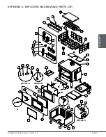
Page 51: ... Appendix 6 EXPLODED DIAGRAM AND PARTS LIST 38 4 A DETAIL A 11 12 10 9 14 5 2 1 6 18 16 15 31 36 35 34 33 37 39 40 41 46 45 30 44 43 43 43 43 43 43 43 43 43 43 43 43 43 43 43 43 42 B DETAIL B 13 C DETAIL C 10 20 21 22 17 29 22 3 23 32 25 24 26 27 28 8 19 7 43 47 ...

Page 52: ... PL65118 GLASS RETAINER 2 9 30025 1 4 20 X 1 2 PAN HEAD QUADREX BLACK SCREW 1 10 30187 STAINLESS WASHER ID 17 64 X OD 1 2 2 11 30898 ROUND WOODEN BLACK HANDLE DULL BLACK FINISH 1 12 31026 PLATED HANDLE RING 1 13 SE53585 GLASS RETAINER KIT WITH SCREWS 12 PER KIT 1 14 SE45928 HARMONY INSTRUCTIONS MANUEL KIT 1 15 30507 BLACK TORX SCREW WITH FLAT HEAD TYPE F 1 4 20 X 3 4 4 16 SE65109 ASH LIP ASSEMBLY ...

Page 53: ...HERMODISC F110 20F 1 38 AC02055 QUICK CONNECT THERMODISC KIT 1 39 21387 TOP AIR DEFLECTOR INSULATION 1 40 PL65505 TOP AIR DEFLECTOR PROTECTOR 1 41 30060 THREAD CUTTING SCREW 1 4 20 X 1 2 F HEX STEEL SLOT WASHER C102 ZINC 3 42 PL36056 2 X 9 1 1 4 REFRACTORY BRICK 2 43 29020 4 1 2 X 9 X 1 1 4 REFRACTORY BRICK HD 17 44 PL65127 FLOORED BRICK RETAINER 2 45 PL65514 SECONDARY AIR TUBE 4 46 21389 C CAST B...

Page 54: ...pair or replace any part or unit after inspection and investigation of the defect The manufacturer may at its discretion fully discharge all obligations with respect to this warranty by refunding the wholesale price of any warranted but defective parts The manufacturer shall in no event be responsible for any uncommon indirect consequential damages of any nature which are in excess of the original...

Page 55: ......

Page 56: ...tional com This document is available for free download on the manufacturer s website It is a copyrighted document Resale is strictly prohibited The manufacturer may update this document from time to time and cannot be responsible for problems injuries or damages arising out of the use of information contained in any document obtained from unauthorized sources ...

Reviews: