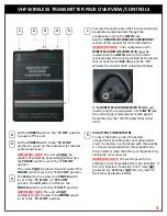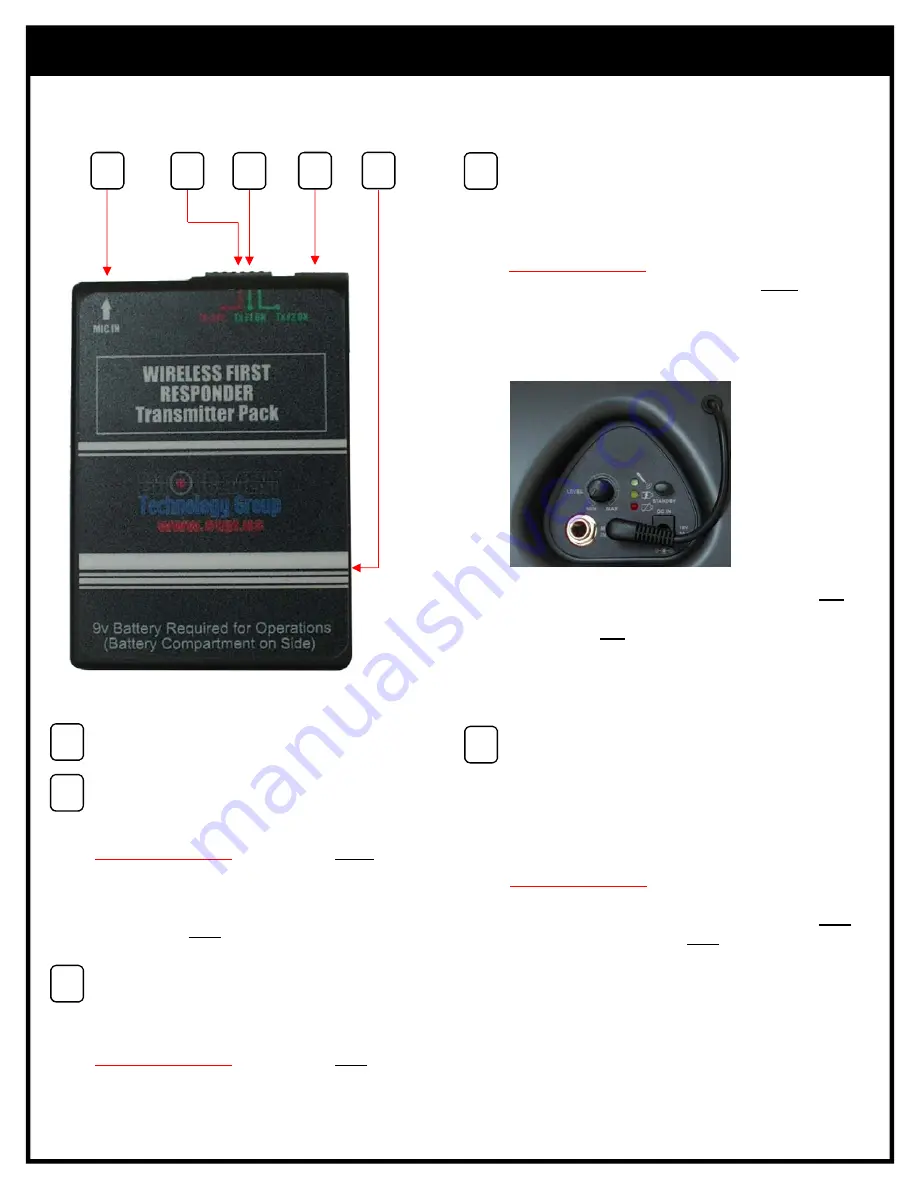
VHF WIRELESS TRANSMITTER PACK OVERVIEW/CONTROLS
3
4
2
5
1
Connect the audio source that is to be wirelessly
transmitted and projected through the
Loudspeaker unit to the
MIC IN
jack.
See the “
REMOTE/RF WIRELESS OPERATIONS
”
section of this manual for more information.
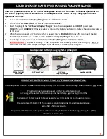
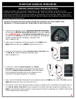
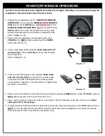
IMPORTANT NOTE
:
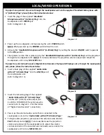
The Loudspeaker unit’s
WIRELESS AUDIO RECIEVER PLUG
must
be
inserted into the
LINE IN
jack for the unit to
receive/project the sound provided by the device
that is connected to
MIC IN
jack of the “
VHF
Wireless Transmitter Pack
” (illustrated below).
If the
WIRELESS AUDIO RECEIVER PLUG
is
not
inserted into the Loudspeaker unit’s
LINE IN
jack,
the unit will
not
receive/project audio signals
transmitted by the “
VHF Wireless Transmitter
Pack.”
The
LED
will turn on when the
POWER
switch
is set to the “
TX F1 ON
” or “
TX F2 ON
”
position. The
LED
will turn off when the
POWER
switch is set to the “
TX OFF
” position.
IMPORTANT NOTE
: The unit will
NOT
wirelessly transmit audio if the
POWER
switch
is set to the “
TX F2 ON
” position.
9V BATTERY COMPARTMENT
To insert the battery, open the battery
compartment by sliding the cover downwards.
Insert the battery in accordance with the polarity
(+/‐) decal contained within the compartment.
Once inserted, close the battery compartment by
sliding the cover upwards.
IMPORTANT NOTE
: The unit ships with a 9v
alkaline non‐rechargeable battery pre‐installed. If
the “
VHF Wireless Transmitter Pack
” does
NOT
power on (i.e.
LED
does
NOT
turn on), install a
fresh/new 9v alkaline battery.
Set the
POWER
switch to the “
TX OFF
” position
to power off the unit.
1
2
4
3
5
Set the
POWER
switch to the “
TX F1 ON
”
position to power on the unit/allow for wireless
audio transmission.
IMPORTANT NOTE
: The unit will
ONLY
be
capable of wirelessly transmitting audio when
the
POWER
switch is set to the “
TX F1 ON
”
position.
The unit will
NOT
wirelessly transmit audio if the
POWER
switch is set to the “
TX F2 ON
” position.
3.

