background image

RF REMOTE/WIRELESS OPERATIONS

CONNECTING TO AN EXTERNAL AUDIO SOURCE:

**

NOTE:

The “

VHF Wireless Transmitter Pack

may also be connected to the 

Lapel

OR

Headset Microphone

AND

an external audio source simultaneously. This allows for the operator to digitally record the audio that is being 
picked up by the microphone/broadcast through the 

Loudspeaker(s)

When the “VHF Wireless Transmitter Pack is 

Configured in this manner one is

NOT

able to use the Remote Volume Control Dial feature.

**

NOTE:

The “

VHF Wireless Transmitter Pack

” may also be connected to an external audio source such as a Digital 

Voice Recorder, MP3 player, CD‐player, etc…to allow the device's audio to be broadcast through the 
Loudspeaker wirelessly.

To connect the “

VHF Wireless Transmitter Pack” 

to an external audio source: 

1.

Insert the male plug of the “

Remote Volume Control Dial

” into either of the female jacks of the “

Stereo 

Splitter Cable

.” 

NOTE:

Check that the Remote Volume Control Dial component is set to a low/mid volume 

output level (positioned to the left).

2.

Insert either male plug of the “

Stereo Patch Cable

” into the external audio device source’s 3.5mm (1/8”) 

HEADPHONE

” or “

EAR

” output jack. 

NOTE:

To connect to an external audio device source with a 6.35mm 

(1/4”) output port, use the 3.5mm‐to‐6.35mm Adapter (provided).

3.

Insert the remaining male plug of the “

Stereo Patch Cable

”  into the female jack of the “

Remote Volume 

Control Dial

.”

4.

Power up  and set the external audio source’s volume output to a mid/high level.

5.

To begin the wireless audio broadcast, press the external audio device’s “play” button and follow steps 2‐8 in 
the “

REMOTE/WIRELESS OPERATIONS

” section of this manual.

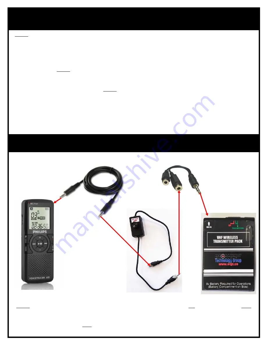
Remote Volume Control Dial

VHF Wireless Transmitter Pack

Stereo Splitter Cable

Digital Voice Recorder

(External Audio Source Example)

Stereo Patch Cable

Connecting an External Audio Source to the 

VHF Wireless Transmitter Pack Set‐Up Diagram

7.

Summary of Contents for Wireless First Responder

Page 1: ... s Standard Components Accessories 1 Loudspeaker VHF Wireless Transmitter Pack Microphone Specifications 2 General Operating Safety Guidelines 3 Loudspeaker Battery Charging 4 VHF Wireless Transmitter Pack Battery Installation 5 Introduction to Radio Frequency RF Remote Wireless Operations 5 Radio Frequency RF Remote Wireless Operations 6 9 Loudspeaker Local Wired Operations 10 ...

Page 2: ...mm Plug Handheld Microphone with 6 35mm Plug 6 35mm Patch Cable with Male Plugs 1 8 3 5mm Patch Cable with Male Plugs Digital Voice Recorder includes USB Transfer Cable and 2 AA Non Rechargeable Batteries Custom Padded Loudspeaker Deployment Case Loudspeaker with Integrated Internal VHF Wireless Receiver includes 12v Rechargeable Battery AC Power Adapter Charger and AC Power Cord VHF Wireless Tran...

Page 3: ...r Adapter Charger 18vdc 3 A Mains Voltage 100 240v 50 60 Hz 1 5 A switching mode adapter INTEGRATED INTERNAL VHFWIRELESS RECEIVER Rx FREQUENCY CHANNEL VHF Frequency 169 445 MHz MODULATION SYSTEM FM POWER SUPPLY Integrated with Loudspeaker Rechargeable Battery POWER CONSUMPTION 25mA Loudspeaker Specifications VHF Wireless Transmitter Pack Specifications Microphone Specifications WEIGHT 6 oz 170 10 ...

Page 4: ...l servicing to Enforcement Technology Group Inc ETGI personnel Servicing is required when a component has been damaged in any way such as power supply cord or plug is damaged liquid has been spilled or objects have fallen into a component component has been exposed to rain or moisture component does NOT operate normally or component has been dropped CAUTION To reduce the risk of electric shock do ...

Page 5: ...elp prevent damage to the Loudspeaker unit s rechargeable battery due to overcharging ALWAYS disconnect the AC Power Adapter Charger from the unit once battery charging is complete When the Loudspeaker unit s 12v rechargeable battery is fully charged the unit may be operated for approx 6 to 8 hours An unlimited Loudspeaker operating time may be achieved when the Loudspeaker is connected to an exte...

Page 6: ...ireless Transmitter Pack and the audio source to which it is to be connected to provide the operator with the ability to remotely increase or decrease the volume output level of the Loudspeaker unit s in which the audio signals are being transmitted to and received by Remote Volume Control Dial If the Remote Volume Control Dial is being used the maximum output volume level that may be achieved is ...

Page 7: ...mitter Pack to the Remote Volume Control Dial and an External Audio Device Source i e Digital Voice Recorder 1 Insert the male plug of the Remote Volume Control Dial into the MIC IN jack located on the top VHF Wireless Transmitter Pack NOTE Check that the Remote Volume Control Dial is set to a low mid volume output level positioned to the left 2 Insert either male plug of the 1 8 3 5mm Patch Cable...

Page 8: ...into either of the female jacks of the Stereo Splitter Cable NOTE Check that the Remote Volume Control Dial component is set to a low mid volume output level positioned to the left 2 Insert either male plug of the Stereo Patch Cable into the external audio device source s 3 5mm 1 8 HEADPHONE or EAR output jack NOTE To connect to an external audio device source with a 6 35mm 1 4 output port use the...

Page 9: ...et the unit s MIC LEVEL dial to greater than 80 during RADIO FREQUENCY RF REMOTE WIRELESS OPERATIONS 2 After the MIC LEVEL dial has been set power up the Loudspeaker by pressing the device s POWER button NOTE The POWER button will turn green signaling that the unit is receiving power 3 To help prevent damage to the Loudspeaker s during use or when operating in inclement weather place the unit insi...

Page 10: ... To avoid harmful feedback during operations NEVER hold the microphone directly in front of a Loudspeaker unit when powered on 2 Check that the Loudspeaker unit s MIC LEVEL dial is set to a low mid volume output level and then power on the Loudspeaker by pressing the unit s POWER button NOTE The POWER button will turn green signaling that the unit is receiving power 3 Set the ON OFF switch located...

Page 11: ...e equipped with a 6 35mm or RCA Composite audio output jack an adapter MUST be used not included 4 Power up the connected Digital Voice Recorder and set the volume output level of the device to a mid high level and press the device s PLAY button to be begin the audio broadcast NOTE Adjust the Loudspeaker s MIC LEVEL dial until the audio broadcast volume output level has been achieved 5 After opera...

Reviews: