background image

CenCon

24 


J-XM 

For indirect fired equipment with DJ (E, S, X) style burners up to size 140. 


BASIC OPERATION 

On a call for heating the combustion blower will be enabled to full speed to prepurge the heat exchanger.  
Once the prepurge time has elapsed the combustion blower speed will reduce to ignition speed and then 
enable the ignition control to start and prove pilot flame, then open the main safety valve (SSOV).  After a 
time delay the J-XM will disable the pilot valve.  The burner is allowed to operate to maintain the requested 
discharge air temperature from the CenCon by modulating the control valve and the combustion blower speed.  
If heating is not required the burner will be disabled and the combustion blower will enter a post purge time, 
and then shut down.   

The J-XM burner expansion module can control either a Maxitrol magnetic style modulating valve or an 
actuator and ball valve.   

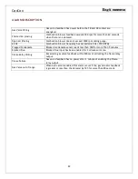
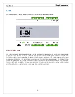
Combustion air blower modulation is controlled by either the CD-XM expansion module.  If using an 
electronically commutated motor (ECM) modulation is directly controlled from the J-XM. 


Summary of Contents for CenCon

Page 1: ...ion adjustment and operation of this unit Read and understand these instructions thoroughly before attempting installation or operation Failure to follow these instructions may result in improper inst...

Page 2: ...Equipment If any errors or omissions are noted please contact the nearest Engineered Air Technical Service Department To ensure warranty is honored only qualified personnel should be employed for ser...

Page 3: ...ING Improper installation adjustment alteration service or maintenance can cause property damage injury or death Read the installation operation and maintenance instructions thoroughly before installi...

Page 4: ...NG ENERGY EFFICIENCY TITLE 24 17 HIGH AMBIENT LOCKOUT 17 INDOOR AIR QUALITY Error Bookmark not defined LOW LIMIT 17 HEATING 17 GAS FIRED HEATING 18 COOLING 18 GENERAL TIMING 18 TEMPERATURE CONTROL 19...

Page 5: ...47 TERMINAL DESCRIPTION 48 ALARM DESCRIPTION 48 CD XM 49 BASIC OPERATION 49 P XM 50 BASIC OPERATION 50 Appendix A Thermistor Output Table 52 Appendix B Maxitrol Valve Adjustments 53 Appendix C Startu...

Page 6: ...quipment it is controlling HARDWARE INFORMATION Control Voltage 24Vac 60Hz Apparent Power Ratings Digital Output Rating 120V 10A CenCon 10 VA Digital Input 24Vac1 J XM G XM M XM 30 VA Analog Output 0...

Page 7: ...rt button then Settings then Network and Internet Then click Ethernet on the left side then Change Adapter Options Click the Ethernet icon and a status page should open Press Properties then Ethernet...

Page 8: ...S The layout of the display screen depends on the age and version of the CenCon The initial release interface display screen example A second release similar to the following has been released Note th...

Page 9: ...CenCon 9 The third release screens have been improved for visibility and tablet use Note the tabs along the top for more screens The background is black This image is grey for printing purposes...

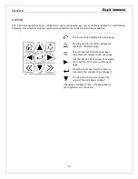
Page 10: ...age Pressing the alarm button changes the display to the alarm page The left and right double arrow keys increment the display to the next page Use the left and right arrows to navigate the location o...

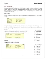
Page 11: ...mper ON Blower ON Alarm Display Pressing the right page advance changes the display to the next status page s Note the top right corner describes which module the variables relate to The sample list t...

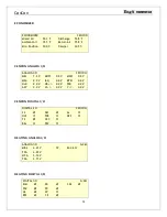
Page 12: ...V Y 0 0 V CENCON DIGITAL I O DIGITAL I O CENCON SA DM AL OLF FbB DES FS OCC BAL DhC HEATING ANALOG I O ANALOG I O G XM MBV 4 41 V CP 24 4 k FbG 4 39 V MCA 3 74 V FbA 3 71 V HEATING DIGITAL I O DIGITA...

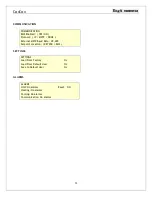
Page 13: ...ol IP MSTP NONE External MSTP Baud Rate 38 400 Setpoint Location KEYPAD EMS SETTINGS SETTINGS Load From Factory No Load From Default User No Save to Default User No ALARMS ALARMS Unit No alarms Reset...

Page 14: ...r end switch Mechanical damper end switch 24 Vac AL DO Alarm Alarm contact for annunciation 24 Vac SA DO Supply air Blower enable contact 24 Vac DM DO Damper actuator enable Two position actuator cont...

Page 15: ...ly operating and the feedback drops 5 below the low air flow set point a low air flow warning is displayed and the 15 second alarm timer is started If the air flow rises above the low flow set point w...

Page 16: ...air temperature changes so does the air density and volume The blower delivers a constant volume of cold air As this air is warmed by the heat exchanger it expands causing the outlet air volume to in...

Page 17: ...umidity sensors are installed in the return and outside air and enthalpy is calculated based on the humidity and temperature readings LOW LIMIT Based on discharge air temperature sensing the low limit...

Page 18: ...ling Refer to the C XM cooling expansion module section The MCW Modulating Chilled Water output is a 0 10Vdc signal with 0V no cool and 10V max cool typically associated with a chilled water coil Reve...

Page 19: ...efer to the field wiring diagram included with the appliance for wiring connections A remote wall sensor S3010W1000 is available for various single or averaging room sensor arrangements Further inform...

Page 20: ...r the VFD feedback drops below the minimum speed for 30 seconds Discharge Air Sensor Failure Discharge Air sensor is outside of its range 60 F to 220 F for 10 seconds or more Ambient Air Sensor Failur...

Page 21: ...ould only connect to the CenCon unpainted ground connection COMMUNICATION WIRING m NOTICE Correctly wiring the internal Modbus communication network is critical to ensuring stable operation Maintain t...

Page 22: ...same unpainted ground termination used by the CenCon panel ground All expansion module intermediate drain wires must be twisted together tightly and taped to secure together and isolate from ground A...

Page 23: ...ected Expansion Module Engineered Air Appliance Type J XM DJ S E X style indirect fired heating up to size 140 G XM DG and DJX indirect fired gas burners sizes 200 and 300 M XM HE direct fired gas hea...

Page 24: ...XM will disable the pilot valve The burner is allowed to operate to maintain the requested discharge air temperature from the CenCon by modulating the control valve and the combustion blower speed If...

Page 25: ...r has been established 24 120 Vac SR1 SR2 DO Safety relay Secondary safety lockout contacts 24 120 Vac FR1 FR2 DO Flame relay Flame relay enable contacts 24 120 Vac FbV DI Feedback valve Feedback sign...

Page 26: ...proper gas valve wiring 2 seconds Blocked condensate 5 minutes Blocked flue 10 seconds trip and 1 minute to alarm Heat exchanger cool down 90 seconds if the discharge air is above 50 10 C else none He...

Page 27: ...gh fire At each stage enter the feedback value for the gas actuator once stabilized Once complete press Start Setup to release COMBUSTION OFFSETS Access the Combustion Setup page by pressing the Right...

Page 28: ...tton and allow O2 levels to stabilize Press Low Fire and release the High Fire button As the burner reduces to low fire observe O2 levels to ensure they do not drop below the high fire O2 setting by m...

Page 29: ...exceeded 60 Hz 3590 RPM Plugged Condensate Blocked condensate sensor reads less then 7k for more than 5 minutes Blocked Flue Blocked flue input has been enabled for 3 minutes or more Flame Relay Wirin...

Page 30: ...s will move to ignition position and then enable the ignition control to start and prove pilot flame then open the main safety valve SSOV Once the pilot flame has proven and the main flame is establis...

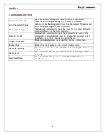
Page 31: ...n air actuator feedback signal to the demand signal 0 10 Vdc MBV AO Modulating ball valve Modulating gas valve actuator output 0 10 Vdc MCA AO Modulating combustion air Modulating combustion air actua...

Page 32: ...2V Enter the actual feedback values into the spaces provided Press in sequence from low to high fire At each stage enter the feedback values for both the gas and air actuators once stabilized Once com...

Page 33: ...gh fire O2 setting by more than 0 3 If this occurs there is air fuel curve error and must be reset with the above steps Press Setup Complete Press to disable Service Mode Return to the home screen by...

Page 34: ...en Air Proving Combustion blower air switch input has no power for 60 seconds after commanding the combustion blower on Combustion blower air switch input has no power for 2 seconds during main flame...

Page 35: ...urner is allowed to operate to maintain the requested discharge air temperature from the CenCon by modulating the control valve If heating is not required the burner will be disabled and then shut dow...

Page 36: ...h Speed High speed fan start contact 24 120 Vac Exl DO Exhaust fan low Single or low speed exhaust fan start contact 24 120 Vac DFR DO Dual Flame Rod Relay output to switch flame rods 24 120 Vac WPu D...

Page 37: ...to be verified if the actuator is replaced For field serviced record all offset values and then set all values to zero for the gas actuators Enter calibration screen and perform calibration setup Ret...

Page 38: ...alarm will not be triggered if we have already passed the purge status and have lit See Low velocity air Switch alarm Low Pressure Sensor If the pressure is greater than the Very low pressure setpoint...

Page 39: ...and off compressor stages to attempt to maintain the discharge temperature setpoint As with all staged systems expect the discharge temperature to fluctuate from setpoint as compressors are turned on...

Page 40: ...Vac C1a DO Cooling stage 1 Output stage 1 cooling powered from common a 24 120 Vac C2a DO Cooling stage 2 Output stage 2 cooling powered from common a 24 120 Vac C3a DO Cooling stage 3 Output stage 3...

Page 41: ...ooling Enable disable mechanical cooling 24 Vac CW1 2 AI Chilled Water sensor 10k Type 2 thermistor Ohms STAGED COMPRESSORS On a call for cooling the compressors will stage on from 1 to 6 The CenCon c...

Page 42: ...ased on ambient temperature TERMINAL DESCRIPTION Terminal Type Name Description Value H N Power Supply 24Vac Grounded Neutral 24 Vac GND Ground Connect to chassis LmA B Modbus Internal Network SCR AO...

Page 43: ...COM Common to output set d Common power relays d 24 120 Vac H7d DO Heating stage 7 Output stage 7 heating powered from common d 24 120 Vac DSw DI Door Switch External safeties input 24 120 Vac HLN Hi...

Page 44: ...evel is controlled by the water level probes Water quality dictates the minimum tank drain cycle times Drain temperature is monitored and cooled with the supply water if required S XM TIMING Dump Sche...

Page 45: ...mary drain valve 24 120 Vac FVS DO Fill Valve Side Enable side tank SHX fill valve 24 120 Vac PV1 PV2 DO Pilot valve Disables the pilot flame once the main burner has been established 24 120 Vac SR1 S...

Page 46: ...e than 1 minute Attempts to drain 15 times then locks out for 2 hours before retrying drain attempt Foaming Alarm If during steam production the low water probe LWP is uncovered in the first 2 minutes...

Page 47: ...r speed heat pipe tilt actuator heat plate damper actuator to discharge setpoint Exhaust temperature is monitored for performance and frost protection The leaving air temperature is primarily for inde...

Page 48: ...or 0 10 Vdc EnH DI Enable energy recovery Enable energy recovery operation 24 Vac Rot DI High Speed Enable Input from rotation sensor 24 Vac CM ByD DO Bypass Damper Dry contact enable bypass damper 24...

Page 49: ...control the combustion motor speed on DJ indirect fired burners in conjunction with the J XM heating module A 3 wire feedback signal from the Engineered Air DJ hall effect speed sensor is used to pro...

Page 50: ...testing for kinked tubing if any pressure is present at the sensor the yellow light will turn on solid for 2 seconds then revert to normal operation It then ignores the pressure sensing output until a...

Page 51: ...CenCon 51 PSw DO Pressure Switch Output contact 24 120 Vac PrS AO Pressure Sensor Pressure sensor output 0 4 w c 0 10 Vdc...

Page 52: ...12814 143 61 7 2343 7 21 7 106939 69 20 6 12182 145 62 8 2252 5 20 6 100218 71 21 7 11590 147 63 9 2165 3 19 4 93909 73 22 8 11030 149 65 0 2082 1 18 3 88090 75 23 9 10501 151 66 1 2003 1 17 2 82670...

Page 53: ...vent holes when the cover cap is removed to allow top loading to function during setup Remove plug once setup is complete and reinstall the cap cover Valve Model Adjustment Top View Gas Flow M420 M52...

Page 54: ...not previously saved will be overwritten The SAVE USER SETTINGS function writes data values from the live system to the permanent memory This process will overwrite any previously saved data and will...

Page 55: ...ombustion As the flue temperature drops and the efficiency increases the amount of water condensing to liquid will also increase Extended chimneys can contribute to condensation problems Increasing th...

Page 56: ...ng valve is located is not pointed directly UP Ideally it enters from the bottom and is located at either side of the burner box and bent to a 90 angle pointed towards the heat exchanger This location...

Page 57: ...ac Man DJ or DG Air Offset for clean burn 2 Near High Fire Multiply High Fire clocking by Ratio X 1 1 and re clock Adjust gas and or air offset values if required Record new clocking value manifold pr...

Page 58: ...1 2 3 4 5 6 Name High Fire Near High Fire Low Fire Near Low Fire Medium Fire 1 Medium Fire 2 Fire 100 90 6 67 10 25 55 Man Press Oxygen O2 CO RPM Air Offset 0 Gas Offset 0 Gas mA Vdc FACTORY CLOCKING...

Page 59: ...ag Date Model Technician Job Name Location Sequence 1 2 3 4 5 6 Name High Fire Near High Fire Low Fire Near Low Fire Medium Fire 1 Medium Fire 2 Fire 100 90 5 10 25 55 Man Press Oxygen O2 CO Air Offse...

Page 60: ...rrect clocking 3 Observe high fire flame for burn quality 4 Reduce to low fire and set flame length Clocking not required Note values below on testbay spreadsheet 5 Finished combustion setup Save valu...

Reviews: