A
CRD
4 of 12
Nov 10
INTRODUCTION
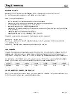
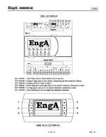
The Engineered Air CRD remote display panel is designed to monitor and control
C-TRAC3 equipment operations via Modbus communication.
CRD Command Capabilities
-
Quickly identify the current operation of the equipment.
-
Ability to scroll to the page associated with specific unit operations.
-
Alarm identification and associated alarm status.
-
Password protection for manual adjustments.
-
Adjustment of manual discharge air setpoints, minimum outside air, unit on/off and time
clock schedules.
-
Change status from Celsius or Fahrenheit.
-
Save setpoints and time schedules to flash memory.
The CRD panel can be ordered with the following control features:
Feature 1: Display only
Feature 2: Control unit on/off, adjust discharge setpoints, damper minimum position &
internal time clock
Feature 3: Remote hand held display c/w options #1 and #2
CRD WIRING
The RS-485 Modbus communication cable from the CRD to the C-TRAC3 is 24awg shielded
twisted pair (STP) with a shunt capacitance of 16pF per foot and 100 ohm characteristic
impedance. Category 5 cable can be used as defined by the EIA/TIA/ANSI 568 specification.
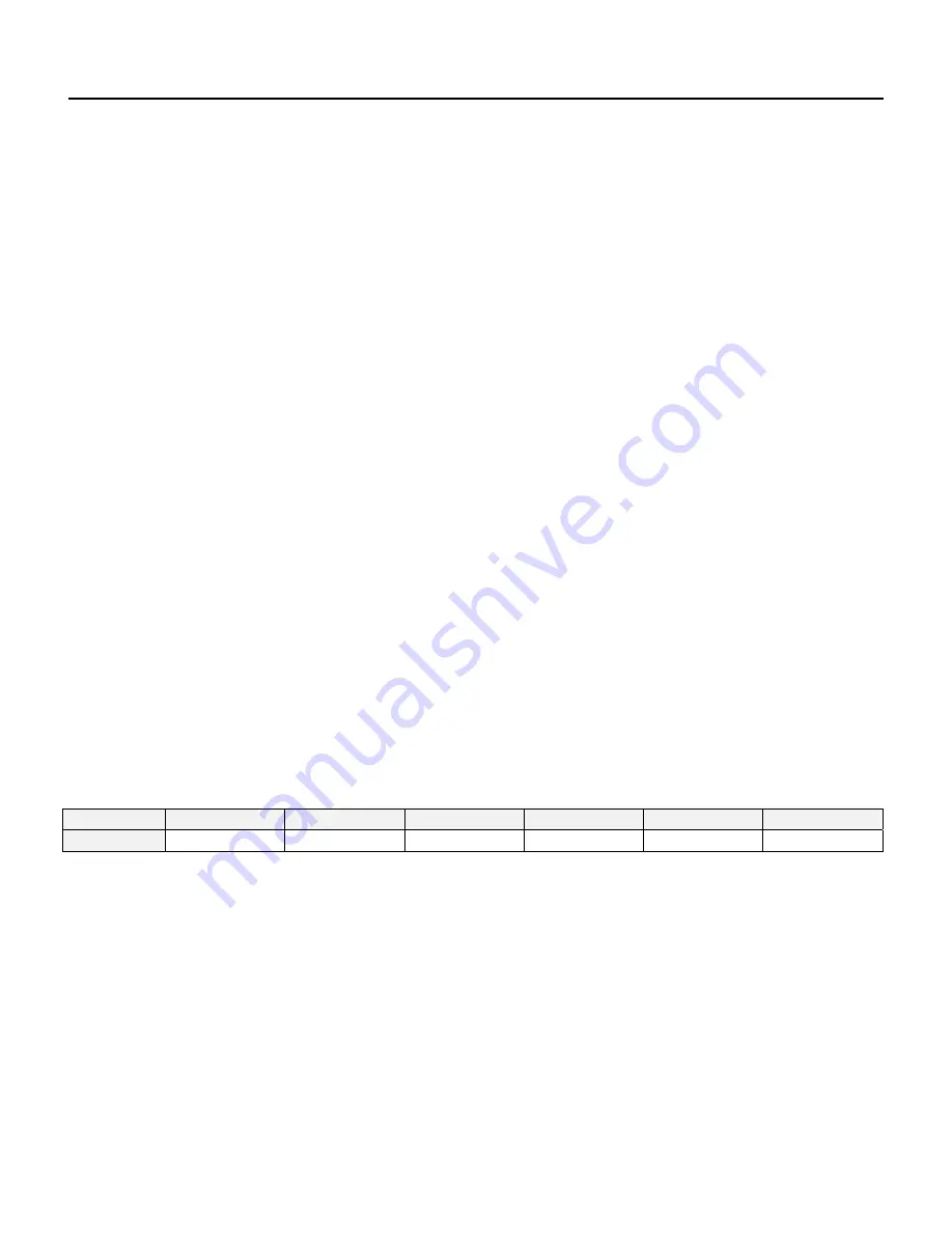
An additional set of 24VAC wires is required to power the remote panel. Refer to the table
below for minimum wire size and maximum distance to the remote panel.
Distance
<100ft.
<150ft.
<200ft.
<300ft.
<350ft.
<450ft.
AWG
#
#20 #20 #20 #18 #18 #16
WIRING REMOTE HAND HELD DISPLAY
Phone cable (RJ45) connection has a maximum distance of 150ft. For greater distances (up
to 600ft), use 2 twisted pair awg/24 shielded cable.
Summary of Contents for CRD C-TRAC3
Page 5: ...A CRD 5 of 12 Nov 10 ...
Page 7: ...A CRD 7 of 12 Nov 10 FIELD WIRING DIAGRAM ...
Page 10: ...A CRD 10 of 12 Nov 10 ...


