April 23, 1999
Page 9
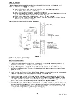
IMPORTANT:THE EXHAUST CAP MUST BE A MINIMUM OF 24" OR 6" ABOVE THE
EXPECTED SNOW DEPTH ON THE ROOF, WHICH EVER IS GREATER, ONCE
THE INSTALLATION IS COMPLETE. VERTICAL PIPE EXTENSIONS OVER
12" MUST BE INSULATED BY A SUITABLE METHOD.
3. Insert the thimble through the roof and secure in place using the mounting bracket or a
suitable support.
4. Install the flue pipe through the thimble ensuring that the minimum clearance accounting for
snow depth is observed. Secure the flue pipe to the inner pipe of the thimble with corrosion
resistant screws and high temperature sealant. The joint between the thimble and flue pipe
must be sealed, and the flue pipe must be flashed to the roof. Attach the exhaust cap to the
end of the flue pipe and secure with 2 corrosion resistant screws and high temperature
sealant.
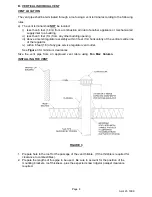
5. Install flue pipe between the vent terminal and the Heater. All pipe joints must be sealed with
high temperature tape and silicone sealant, and secured with corrosion resistant sheet metal
screws. High temperature tape shall be wrapped two full turns around each joint. Ensure the
flue pipe is adequately supported for vertical venting as per CAN1-B149 codes latest
addition.
C. OPTIONAL VERTICAL VENT TERMINAL
Your power vented Heater may be vented using an existing Type B vent terminal provided the
following conditions are met.
1. Ensure the installation meets local venting codes and CAN1-B149 codes latest edition.
2. Size vent pipe from an approved vent table using Fan Max Column. (Tables may be found
in CAN1-B149 codes).
3. Ensure that the only large diameter vent pipe is the vent terminal itself, i.e. the expansion
must take place at the vent terminal.
4. Ensure the vent terminal is in good condition, clean, and gas tight. If there is damage or if
the vent terminal is corroded, a vent terminal as described early is recommended.
5. Install flue pipe between the existing vent terminal and the Heater. All pipe joints must be
sealed with high temperature tape and silicone sealant and secured with corrosion resistant
sheet metal screws. WE RECOMMEND USING 3M TYPE 433 OR 363 ALUMINUM TAPE.
High temperature tape shall be wrapped two full turns around each joint. Ensure the flue
pipe is adequately supported for vertical venting as per CAN1-B149 codes, latest addition.
RECOMMENDED METHOD OF INSULATING THE SINGLE WALL VENT PIPE (A 6" clearance
to combustible material must be maintained).
1. It is required that any vent connector pipe which runs through unheated space be insulated
with 1" fibreglass insulation as described in FIGURE # 4 and FIGURE # 5. In heated space it
is acceptable to omit insulation.
2. After the vent pipe has been properly sealed and properly supported, the one piece pipe
insulation may be installed.
3. First insulate all the straight sections of vent pipe but do not fasten.
4. Vent pipe elbows may be insulated by miter cutting a straight section of one piece pipe
insulation.
5. Once the entire length of vent pipe has been enveloped, peel off the release paper and seal
all joints. Seal by pressure with hands working from the centre out. (See figure 4).
6. Remove the release paper from the butt strips and wrap snugly around butt joints. (See
figure 5).

