April 23, 1999
Page 6
.VENTING
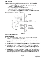
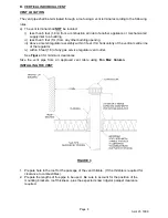
There are 3 arrangements by which this appliance may be vented:
A. SIDEWALL INDIVIDUAL VENT
B. VERTICAL INDIVIDUAL VENT
C. OPTIONAL VERTICAL VENT
Details of each method follow. Note carefully the regulatory requirements for the one you
choose.
FOR ALL METHODS ENSURE COMPLIANCE WITH THE FOLLOWING - FAILURE TO DO SO
MAY RESULT IN A HAZARDOUS CONDITION AND WILL VOID THE WARRANTY.
A) The vent system should be checked once every year by qualified service personnel.
B) This Heater shall not be connected to a venting system serving any other gas, liquid,
or solid fuel fired appliance or fireplace.
C) The venting system shall be sized so that the vent area is not less than that of flue
outlet of the Heater.
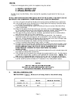
D) Pipes for flue gases must be sized as per minimum vent size table (page 3 - figure
1). On smaller units where the flue discharge opening is smaller, the transition to the
larger size pipe must be made at the Heater and not at the vent terminal.
E) The pipes for flue exhaust must be of 24 GA. galvanized steel or a material with at
least equal strength and corrosion resistance.
F) Keep the vent connector pipe as short and direct as practical. The maximum
equivalent length of the vent pipe is not to exceed 25'. The minimum length of vent
pipe is 6'. One 6" diameter 90 degree elbow is equivalent to four feet of straight pipe.
Be sure to consider all elbows when planning the vent.
G) All connections between the Heater and the vent terminal must be secured with two
corrosion resistant sheet metal screws, rivets, or solder.
H) All joints and seams between the Heater and the vent terminal must be sealed. Tape
or solder may be used to seal the flue pipe providing the tape may be used at 550
o
F.
WE RECOMMEND USING 3M TYPE 433 OR 363 ALUMINUM TAPE. ALL FLUE
PIPING MUST BE CHECKED FOR GAS TIGHTNESS FOLLOWING
INSTALLATION.
I)
In all cases maintain a minimum of 6" clearance between the vent connector pipe and
any adjacent combustible construction.
J) The exhaust cap to be used is the exhaust cap supplied with the unit. For information
on alternate exhaust caps, contact your Engineered Air representative. NOTE: Only
CGA approved Engineered Air supplied exhaust caps are acceptable as alternates.
K). If the vent pipe passes through a combustible wall or roof, a ventilated metal thimble
must be used to provide a minimum 2" clearance to the combustible material.
NOTICE
SPECIAL VENTING SYSTEM REQUIRED
RATED FLUE GAS TEMPERATURE 450
o
F (232
o
C)
RATED VENT PRESSURE NON POSITIVE
A.
SIDE WALL INDIVIDUAL VENT
INSTRUCTIONS: Figure 1: Minimum Vent Sizing Table for Side Wall Venting
Series
Model
Minimum Vent Size
XE (DH) - FP - PV
65 - 255
4"
XE (DH) - FP -PV
320
6"

