background image

A       


DJM3 

IOM-17 

                       10 of 27                                                                 Mar 99 R3 


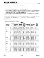
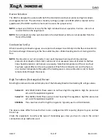
The DJM3 is designed to use either of the following as a setpoint: 


The setpoint mounted on the face of the DJM3 (range of 50‐95°F (10‐35°C)). If the DJM3 face 
mounted set‐point is used, terminals “SP and S” must be jumpered; or 


The Johnson Controls TE 6100‐960 set‐point (range of 50‐85°F (10‐29°C)). If the TE 6100‐960 is used 
as a set‐point, “S to SP” is not jumpered and the TE 6100 must be wired: 


TABLE 7


TE 6100 Wires 

DJM3 Terminals 

Violet (not used) 

‐ 

Red (not used) 

‐ 

Grey 

Wired to terminal U 

Blue  

Wired to terminal M 

Orange 

Wired to terminal S 


DISCHARGE


TEMPERATURE


SENSOR


(D


TEMP)


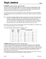
The DJM3 uses the discharge sensor for both temperature control and low limit. Because of this, the 
DJM3 will not operate with a faulty discharge sensor. If the discharge sensor resistance is greater than 
4000‐ohms or less than 880‐ohms, the unit will lock out either on low limit or bad temperature sensor. 
 

MODULATING


ROOM


RESET


(continuous


blower


operation


only)


DIP switch 3 must be "on". This option also requires a TE 6100 wired: 

TABLE 8 

TE 6100 Wires 

DJM3 Terminals 

Red (not used) 

‐ 

GREY 

Wired to terminal V 

VIOLET 

Wired to terminal X 

ORANGE 

Wired to terminal Y 

BLUE 

Wired to terminal Z 

 
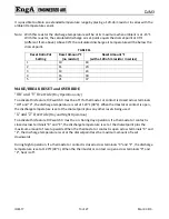
If DIP switch 3 is on and the TE 6100 is not wired to the correct DJM3 terminals, the DJM3 will reset the 
discharge temperature down as it thinks that the room sensor is very warm. The room temperature 
requirements can increase or decrease (reset) the calculated discharge air set‐point. 
 
Note: If room reset calling, the “calculated” discharge temperature setpoint will vary from the setting 
of “master” setpoint. 


The room‐reset feature is activated by DIP switch 3. 


Room sensor calibration pot is Room Cal Pot. 


Room reset band is 

3°F (fixed). 


The “room reset band” means a room temperature error of just 3°F will result in a maximum reset of 
the discharge air set point. The actual amount reset (in degrees) varies as per both the setting of Pot 
Reset Ratio and the discharge set point. The calculated discharge air set point (dial s reset) is 
limited between 48 and 120°F.  
 

Summary of Contents for DJM3

Page 1: ...D OFFICE AND FACTORY CANADIAN EASTERN FACTORY 1401 HASTINGS CRES SE CALGARY ALBERTA T2G 4C8 Ph 403 287 2590 Fax 888 364 2727 32050 W 83rd STREET DESOTO KANSAS 66018 Ph 913 583 3181 Fax 913 583 1406 11...

Page 2: ...velope which also contains the Operation Installation and Maintenance manual s This package is for copying then should either be returned to the appliance or stored in a safe place The other set is at...

Page 3: ...A DJM3 IOM 17 3 of 27 Mar 99 R3...

Page 4: ...WER OPERATION ONLY 12 MAKE BREAK RESET AND OVERRIDE 13 OR and V Override Day Operation only 13 X and Z Override Day and Night Operation 13 OPERATION 14 DAY NIGHT OPERATION 14 FAN CONTROL 14 DAMPER CON...

Page 5: ...ould be used in conjunction with the unit function sheet s and the DJ E S DG or DJX series Installation Operation and Maintenance manuals The DJM3 is designed to control only Engineered Air equipment...

Page 6: ...SA Supply air fan enable output CB1 Combustion blower motor input CB2 Combustion blower motor speed control output PV1 PV2 Pilot valve disable contact dry VFB120 Main gas valve feedback SSOV hot inpu...

Page 7: ...t TABLE 3 LIGHT LED ON 2 SEC FLASH 1 SEC FLASH INT FLASH 1 LL LOCKOUT LL BYPASS D SEN OPEN 2 PRE PURGE PP PROBLEM 3 HEAT CALL HT SW OPEN SERVICE MODE 4 IGN ENABLE FLAME FAIL 1 ON The appliance has bee...

Page 8: ...l The DJM3 did not receive a main gas valve SSOV feedback signal into terminals VFB24 or VFB120 Normal operating status OFF ADJUSTMENT POTS There are a number of setting and calibration potentiometers...

Page 9: ...rm up time 30 seconds Cool down time 60 seconds Low limit bypass 5 minutes Flame Failure 90 seconds TEMPERATURE CONTROL CALCULATED SETPOINT SPC The DJM3 is designed to be a discharge air temperature c...

Page 10: ...RESET continuous blower operation only DIP switch 3 must be on This option also requires a TE 6100 wired TABLE 8 TE 6100 Wires DJM3 Terminals Red not used GREY Wired to terminal V VIOLET Wired to term...

Page 11: ...iate wiring ROOM RESET AUTHORITY TABLE TABLE 9 Discharge Set Point Reset Ratio Pot Maximum Temp C Minimum Temp C Reset Band Width C Maximum Temp F Minimum Temp F Reset Band Width F 15 5 C 60 F 1 25 9...

Page 12: ...of the larger board just below the DIP switch block and beside Pot Reset Ratio This is a 1 watt 680 ohm resistor colours blue grey brown gold BMS reset is not truly linear Reset will usually begin at...

Page 13: ...re DIP switch 3 must be off If a thermostat or contact is closed across terminals OR and V the discharge temperature is set at 120 F 49 C When thermostat or contact is open the discharge temperature i...

Page 14: ...d as the low limit sensor If the discharge sensor resistance is too high or open circuit the DJM3 perceives a low limit fault and locks off DJM3 DAMPER CONTROL The inlet damper actuator s is enabled t...

Page 15: ...the setpoint dial will manually set the burner to any firing rate When in service mode the supply air fan may need to be activated manually Note DO NOT leave DJM3 in service mode burner will not cycle...

Page 16: ...hat smell carbon and or an excessive amount of water in the flue Care should be taken to set burners up properly Note that temperature of the air and fuel may have a great affect on the set up selecte...

Page 17: ...urn the Service Pot fully counter clockwise to achieve low fire Adjust the Low Fire Pot until the low fire speed on the combustion fan motor is 1250 RPM 10 RPM 20 8 Hz for 10 1 set up or 1195 RPM 5 19...

Page 18: ...an create sooting of burner parts and the heat exchanger If the locking ring is missing drop one drop of Loctite thread locker onto the brass screw threads Series 50 M550 M650 AND ES350 High Turndown...

Page 19: ...he valve is to be adjusted fully clockwise no bypass Series 50 M550 M650 ES350 These valves do not have high fire regulators High fire pressure is set up at the appliance regulator This series of valv...

Page 20: ...and the voltmeter The millivolt reading should be increasing At the point where it begins to fall you should stop reducing pressure and return to the high spot NOTE The fall in pressure could only be...

Page 21: ...At 3 5 O2 will appear yellow from behind the burner However if you could view it from the other side of the burner you would see blue as the flame lengthens out Low Fire At 16 O2 the flame will likel...

Page 22: ...from the tachometer sensor Hall Effect sensor that is not consistent with the combustion blower status If there is a call for heat and the combustion blower is not running the DJM3 has likely detected...

Page 23: ...the OR terminal is used the wire to terminal OR must be removed 2 Depending on which setpoint control method is used a Johnson Controls TE 6100 i Set Johnson Controls TE 6100 setpoint to 21 C ii Read...

Page 24: ...voltage is equal to the number of C maximum reset 6 Return the DIP switches to their normal position SENSOR TABLE Sensor Resistance Chart for TE 6100 960 and TE6000EA3 Table 13 C F Resistance C F Resi...

Page 25: ...n Starts after 30s Normal Operation Fan Starts after 30s 24 Vac on terminal K Equipment in Night mode fan operation is intermittent 24 Vac on terminal FS Restore power to terminal FS If burner fires f...

Page 26: ...Purge light 2 SEC FLASH Faulty DJM3 Faulty combustion fan No output from terminal CB Speed Sensor Problem Combustion fan running with 5 Vdc across terminals YS and DJM3 fuse failure or faulty DJM3 Tu...

Page 27: ...A DJM3 IOM 17 27 of 27 Mar 99 R3 UPGRADING DJM3 2 OR 3 3 to DJM3 4...

Reviews: