A
DJM3
IOM-17
11 of 27 Mar 99 R3
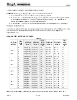
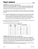
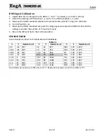
To determine the amount of reset available refer to Table 9.
EXAMPLE
: DJM3 setpoint 70°F; pot #5 set at 3; room thermostat set 75°F.
If room thermostat sensor is at 75°F ‐ no reset, discharge at 70°F.
If room sensor is 3°F cold (72°F), discharge is reset up full amount of its authority (+20) to 90°F.
If room thermostat was at 73°F then
of the reset would be used (
* 20 is approx. 14°F),
added on to the set‐point of 70°F giving discharge of 84°F.
If room sensor is 3°F hot (78°F) full reset down will lower the discharge 13° (57°F discharge).
Multiple Room Sensors
Four sensors can be wired to give an average reading of room temperatures to the DJM3 control. They
must be wired in a series/parallel arrangement. Refer to main or field electrical diagram for
appropriate wiring.
ROOM
RESET
AUTHORITY
TABLE
TABLE 9
Discharge
Set‐Point
Reset
Ratio
Pot
Maximum
Temp. °C
Minimum
Temp. °C
Reset
Band
Width
°C
Maximum
Temp. °F
Minimum
Temp. °F
Reset
Band
Width
°F
15.5°C
60°F
1
25 (+9.5)
12 (‐3.5)
13
77 (+17)
54 (‐6)
23
2
26 (+10.5)
11.5 (‐4)
14.5
79 (+19)
53 (‐7)
26
3
28 (+12.5)
10.5 (‐5)
17.5
82 (+22)
51 (‐9)
31
4
33 (+17.5)
9 (‐6.5)
24
91 (+31)
48 (‐12)
43
5
38 (+22.5)
9 (‐6.5)
29
100 (+40)
48 (‐12)
52
21°C
70°F
1
29 (+8)
16 (‐5)
13
84 (+14)
61 (‐9)
23
2
30 (+9)
15 (‐6)
15
86 (+16)
59 (‐11)
27
3
32 (+11)
14 (‐7)
18
90 (+20)
57 (‐13)
33
4
37 (+16)
11 (‐10)
26
99 (+29)
52 (‐18)
47
5
40.5 (+19)
9 (‐12)
31.5
105 (+35)
48 (‐22)
57
27°C
80°F
1
33 (+6)
21 (‐6)
12
91 (+11)
70 (‐10)
21
2
34 (+7)
19 (‐8)
15
93 (+13)
66 (‐14)
27
3
35.5 (+8)
18 (‐9)
17.5
96 (+16)
64 (‐16)
32
4
39 (+12)
15 (‐12)
24
103 (+23)
59 (‐21)
44
5
44 (+17)
11 (‐16)
33
111 (+31)
52 (‐28)
59
32°C
90°F
1
38 (+6)
25 (‐7)
13
100 (+10)
77 (‐13)
23
2
38 (+6)
23 (‐9)
15
101 (+11)
74 (‐16)
27
3
40 (+8)
22 (‐10)
18
104 (+14)
72 (‐18)
32
4
44 (+12)
18 (‐14)
26
111 (+21)
64 (‐26)
47
5
47 (+15)
13 (‐19)
34
116 (+26)
56 (‐34)
60
NOTE:
The above table is not linear and reset up and down is equal at a set‐point of about 82°F

