A
DJM3
IOM-17
23 of 27 Mar 99 R3
INDUCED
VOLTAGE
ON
REMOTE
CONTROL
WIRING
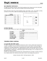
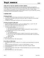
The DJM3 control is calibrated at the factory and this calibration will satisfy most applications.
Occasionally impedance from long wiring runs or induced voltage on the remote wiring cause it to be
out of calibration. To recalibrate refer to the following section. To check for induced voltages,
disconnect all of the field wiring in question from the DJM3.2 while the unit is left operating, and check
for AC volts across each questionable wire and ground.
CALIBRATION
Discharge
Sensor
1.
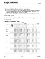
Accurately measure the discharge air temperature at the temperature sensor in °C.
2.
Read the DJM3 discharge temperature by reading the voltage at multimeter test point DTEMP.
Using a DC voltmeter
3.
If a difference is found adjust the D SEN CAL Pot to match to the two values
Discharge
Setpoint
Calibration
1.
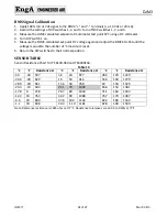
Record the settings of DIP switches 1, 2, and 3. Turn off DIP switches 1, 2, and 3. If the “OR”
terminal is used, the wire to terminal “OR” must be removed.
2.
Depending on which setpoint control method is used:
a)
Johnson Controls TE 6100
i)
Set Johnson Controls TE 6100 setpoint to 21°C
ii)
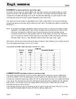
Read the DJM3 Discharge setpoint at multimeter test point SPC using a DC voltmeter.
iii)
Adjust the DIS SP CAL POT to match the reading.
b)
DJM3 Built in Dial
i)
Turn setpoint dial to 21°C.
ii)
Read the DJM3 Discharge setpoint at multimeter test point SPC using a DC voltmeter.
iii)
Loosen the set‐screw on the setpoint knob and move the knob marker to match with the
measured value.
iv)
Tighten set‐screw.
For either of the above:
3.
Return the DIP switches to their normal position.
Room
Sensor
Calibration
1.
Accurately measure the room or return air in
°C
and set the room setpoint dial to the measured
value.
2.
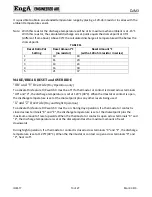
Record the settings of DIP switches 1, 2, and 3. Turn off DIP switches 1, 2, and 3.
3.
Read the DJM3 Discharge setpoint at multimeter test point SPC using a DC voltmeter.
4.
Turn DIP switch3 on
5.
Read the DJM3 Discharge setpoint again and adjust the ROOM CAL Pot to match the same voltage
measured in step 3.
6.
Return the DIP switches to their normal position.

