A
DJM3
IOM-17
24 of 27 Mar 99 R3
BMS
Signal
Calibration
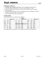
1.
Apply 100% mA or Vdc signal to the DJM3 “+” and “‐” terminals (i.e. 10 Vdc or 20 mA).
2.
Record the settings of DIP switches 1, 2, and 3. Turn off DIP switches 1, 2, and 3.
3.
Measure the DJM3 calculated setpoint at multimeter test point SPC using a DC voltmeter.
4.
Turn DIP switch 1 on.
5.
Measure the DJM3 calculated set‐point DC voltage again and adjust the BMS CAL Pot until the
voltage is equal to the number of °C maximum reset.
6.
Return the DIP switches to their normal position.
SENSOR
TABLE
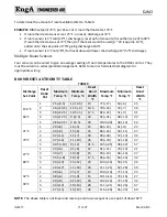
Sensor Resistance Chart for TE 6100‐960 and TE6000EA3.
Table 13
˚C
˚F
Resistance Ω
˚C
˚F
Resistance Ω
˚C
˚F
Resistance Ω
‐40
‐40
597
4.4
40
877
48.9
120
1229
‐34.4
‐30
629
10
50
916
54.4
130
1279
‐28.9
‐20
661
15.6
60
958
60
140
1329
‐23.3
‐10
694
21.1
70
1000
65.6
150
1381
‐17.8
0
728
26.7
80
1043
71.1
160
1433
‐12.2
10
763
32.2
90
1088
76.7
170
1487
‐6.6
20
800
37.8
100
1134
82.2
180
1542
‐1.1
30
838
43.3
110
1181
87.8
190
1599
Note: Reference resistance is 1035 ohms at 77˚F. Resistance tolerances are ±0.05 to 0.15% at 77˚F.


