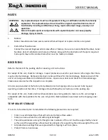
A
XES SC MANUAL
IOM-58
10 of 30
June 14 R5
b)
Carefully slide the fan section back until the back and sides of the heat fan section are flush. This
will lock the two pieces together at the back as the locking clip engages. Do not damage foam tape
which acts as air seal between sections.
c)
Remove the outer fan door, vent pipe, shipping cardboard and inner fan door. Drive sheet metal
screws from the fan section into the heat section. Holes are provided in the front vestibule at sides
for locating two sheet metal screws.
d)
The unit is now one piece locked together at back by clip and at front by two sheet metal screws.
e)
Motor wires and upper limit control wires are clipped at top of heat section. Feed both of these
wire pairs into the fan compartment, through the hole provided. Wires should be neatly clipped in
place and taut so they will not contact the hot draft hood parts.
f)
Connect the motor wires to the motor and upper limit control wires to the limit as shown on wiring
diagram.
g)
Install the inner fan door.
h)
Connect the vent pipe between the heat section and the top collar of the fan section. The vent
connector piece should be secure and located at the top of the fan section.
i)
Inspect and test the electrical components and motor operation.
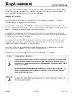
SEPARATED COMBUSTION
Warning:
Separated combustion equipment is not designed or approved for use in
atmospheres containing flammable or chlorine vapors.
Warning: The installation of separated combustion systems must be completed by
qualified persons in accordance with all federal, state, provincial and/or local
codes.
Warning:
Do not operate this heater without all combustion air and flue gas piping
installed.
The heater shall not be connected to a venting system serving any other gas, liquid or solid fuel fired
appliance. Installation shall be in accordance with the requirements of authorities having jurisdiction and
ANSI Z2231/NFPA 54 or CSA B149.1. The vent shall be installed in such a manner that access to the
appliance or unit rating plate is not obstructed.

