A
XES SC MANUAL
IOM-58
23 of 30
June 14 R5
OPERATION
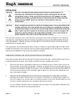
Warning:
This unit is connected to high voltages. Electrical shock or death could occur if
instructions are not followed. This equipment contains moving parts that can start
unexpectedly. Injury or death could occur if instructions are not followed. All work
should be performed by a qualified technician. Always disconnect and lock out power
before servicing. DO NOT bypass any interlock or safety switches under any
circumstances.
Warning:
Proper commissioning and start-up of the air handling system is the responsibility of the
installing contractor. It is recommended that an air balance be completed by a certified
air balancing contractor to insure the air volume being delivered matches the unit rating
plate. Failure to perform a proper air balance can cause injury or death, damage to the
equipment, property damage, system operational problems, or be a cause of poor air
quality. Moisture carry over can result from improper air flow.
This unit may incorporate one or more functions and a variety of controls and options to suit individual
requirements. A description of the unit functions and options is shown on the Electrical Data Sheet and
unit wiring diagram. Carefully check your wiring diagram to verify that all remote controls are properly
located and correctly field wired.
Some equipment may contain programmable unitary controllers or programmable logic controllers (PLC).
Additional information can be obtained from the specific programmable control manufacturer. Often this
information is available from the control manufacturer’s website.
COMBUSTION AND FINAL UNIT CHECK FOR UNITS WITHOUT TRAC CONTROLS
The heater has been test fired in the factory for firing rate and combustion. Field conditions may require
small adjustments to be made. These checks should be done by a qualified service man.
1.
When the main flame is established, check the gas manifold pressure at the test point nearest the
burner with the unit operating at high fire. Check the name plate for the correct manifold pressure
and adjust the appliance regulator if necessary. The unit inlet gas pressure should not go below the
minimum pressure shown on the nameplate when at high fire. Ensure that the temperature rise
does not exceed nameplate.
2.
Check CO and O
2
reading at maximum and minimum inputs shown on name plate. CO should
generally not be above 200 ppm and a very maximum of 300 ppm. O
2
reading should range from
4% to 7% at high fire on all units. Low fire combustion values are found on the table below for units
that have constant combustion air or variable combustion air damper.
For units X-TRAC controllers refer to Combustion Set-Up section in the Installation, Operation and
Maintenance Manuals for the respective controls.


