A
G-TRAC MANUAL
IOM-24
Page 6
March 1999 R1
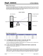
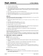
Multiple Room Sensors
Four sensors can be wired to give an average reading of room temperatures to the Trac cntrol. They must
be wired in a series/parallel arrangement. The drawing shows a circuit making use of the built in sensor in
the T#6100 Johnson Sensor/set point assembly and using TE6000 sensors for the other three. (The other
three could also be TE6100, just using the sensor wires)
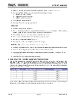
Room Reset Authority Pot
Position
Reset Amount
Position
Reset Amount
1
±9°F
4
±18°F
2
±11°F
4.5
±23°F
3
±14°F
5
±32°F
VII. TO TEMPORARILY DRIVE THE UNIT TO HIGH OR LOW FIRE
To force a G-TRAC to full heat, short the discharge sensor "Q" and "U".
To force a G-TRAC to low fire substitute a 1000 ohm resistor for the discharge sensor and adjust the set-
point pot to a point that just turns the heat call light on.
VIII. G-TRAC DISCHARGE TEMPERATURE SENSOR/SETPOINT CALIBRATION
Calibration is best done with supply fan on.
Method 1
Bring the G-TRAC to a stable discharge temperature by the following steps after disconnecting any override
devices. If the room reset option is wired on the unit you are working on you must disconnect the jumper
between “RR and +”. Note that all other potentiometer settings should be finalized before continuing with
this procedure. Calibration may be affected if other pots are adjusted after this procedure is complete.
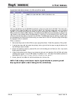
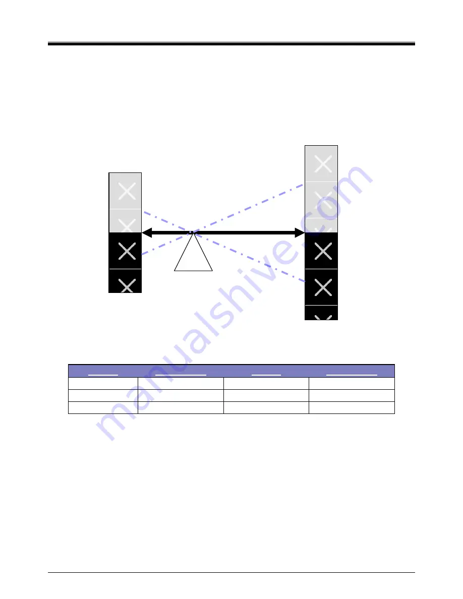
Pivot
Point
RESET CONTROL
Discharge Temperature
Warm Discharge
Discharge Air Set Point
Cool Discharge
Room Hot
Room Cold
Room Temperature
Room Set Point
Summary of Contents for G-TRAC 1.1
Page 23: ...IOM 24 Page i March 1999 R1...

