A
G-TRAC MANUAL
IOM-24
Page 7
March 1999 R1
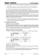
Jumper the combustion blower.
Jumper the flame relay terminals.
Place a Q209 Honeywell 140 ohm pot on the V9055 valve to modulate it to a fixed position and allow it
to run until discharge air temperature is stable in the modulated area of the valve stroke and between
55 to 90ºF.
Place a thermometer within one inch of the discharge sensor.
Set the TE 6100-960 set-point dial
(or internal set point if used)
to match the reading on the thermometer.
Adjust the G-TRAC calibration pot P1 until the heat call light just goes out.
Method 2
This description assumes the control is operating as an internal set-point control.
(SP and P are jumped.)
This
method does not correct for remote wire resistance.
Disconnect any external override controls
(if room override option is used remove the "RR and +" jumper to
disable it.)
Set all pots to their required positions
(except P1 and P3)
.
Allow the G-TRAC to run until it completes its pre-purge.
Set pot 4 to 70°F
(21°C)
(auxiliary set point)
.
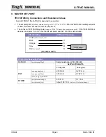
Connect a 1005-ohm resistor in place of the discharge sensor. A resistor of this value represents a 70º-
discharge temperature. It should be wired to terminals "Q and U".
Adjust pot 1 until the heat light just shuts off. This places the G-TRAC in its dead band area.
Return the control to normal.
Assuming the control is operating with an external set point. Follow the above instructions except set the
remote TE 6100-960 sensor to 70°F
(21°C)
.
If there is concern about doing this calibration in cool weather and drawing cold air into the building,
disconnect the wires to "FR and SA" to shut off the heat and supply air fan while the calibration is done.
IX. ROOM RESET CONTROL CALIBRATION
Method 1
(Most accurate method)
Remove the jumper between “RR and +”.
Remove the wires connected to “Z and X” and measure the resistance on them. Reconnect the wires to
“Z and X”.
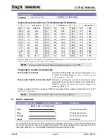
Compare the resistance to that shown on the TE 6000 Sensor chart located in this manual.
Adjust the reset set point to the same value found in the above step.
Measure the voltage across “RR and +” and adjust pot 3 until the meter just reads a zero value
(or in
absence of a meter, a less accurate method is to jumper “RR” and “+” and adjust pot 3 until the heat call light
just goes off)
.
Reconnect wiring to “RR and +”.
Method 2
(Does not correct for remote wire resistance)
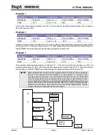
Disconnect all room reset control terminals “V, X, Y and Z” from the G-TRAC. Connect a jumper across
the G-TRAC terminals "RR and +".
Summary of Contents for G-TRAC 1.1
Page 23: ...IOM 24 Page i March 1999 R1...

