A
G-TRAC MANUAL
IOM-24
Page 8
March 1999 R1
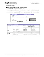
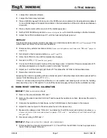
Place a 1005-ohm resistor across G-TRAC terminals "X and Z" to simulate 70°F
(21°C)
.
Connect the TE 6100-960 set-point to the G-TRAC terminals as follows:
1. BLUE to G-TRAC terminal Z
2. ORANGE to G-TRAC terminal Y
3. GREY to G-TRAC terminal V
Turn the TE 6100-960 dial to 70°.
Adjust pot 3 until the heat light just shuts off
Method 3
Disconnect jumper from “RR and +”.
Set the discharge air calibration using a 1005-ohm resistor
(to simulate 70°F)
in place of the discharge
sensor. Adjust set point just short of where the heat call light comes on.
Accurately measure the room temperature next to the room sensor.
Set the room set point to the same temperature as was measured.
Ensure the jumper is re-installed "RR" to "+".
Adjust pot 3 until the heat call light is just short of coming on.
Method 4
(May correct minor electrical noise on remote wire)
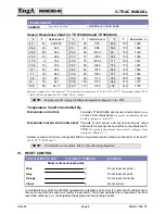
Disconnect wires to terminals “Z and X” and measure the resistance on them. Reconnect the wires.
Compare the reading with the TE 6000 resistance chart in this document.
Adjust the room reset set-point dial to the same value as related to the chart.
(Also ensure “RR and +”
are jumpered.)
Adjust pot 3 until the Heat Call light just comes on.
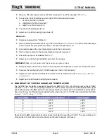
X. BMS RESET OF THE DISCHARGE AIR TEMPERATURE
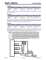
The G-TRAC has the ability to accept an input from a BMS 0-10 VDC or 4-20 ma signal on the G-TRAC
terminals "+ and -". This is not optically isolated. Pot "P7" sets the amount of override that the BMS signal
will be allowed when the BMS signal is at its highest. Setting 1 is about ±32ºF and setting 5 is about ±60ºF.
The amount of reset authority may be slightly higher when using a 0 to 10 VDC reset signal from the BMS.
(Setting 1 = ±40ºF; setting 5 = ±75ºF).
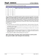
Pot 7 Setting
Reset Value With 0-10 VDC Signal
4-20 ma Signal
5
+ 75°F
+ 60°F
4
+ 68°F
+ 54°F
3
+ 60°F
+ 48°F
2
+ 50°F
+ 40°F
1
+ 40°F
+ 32°F
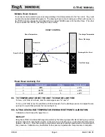
Reset from the BMS signal will not be truly lineal. It will start to reset about 3 VDC. The reset will begin to
ramp gently at 3 volts and ramp more steeply as the reset voltage is increased.
Summary of Contents for G-TRAC 1.1
Page 23: ...IOM 24 Page i March 1999 R1...

