A
G-TRAC MANUAL
IOM-24
Page 9
March 1999 R1
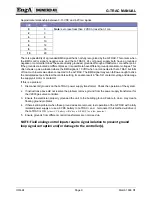
Approximate relationship between 0-10 VDC and 4-20 ma signal.
VDC
ma
0
0
Note:
zero reset less than 2 VDC or less than 1 ma
2
3
4
8
5
10
6
12
8
16
10
20
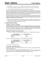
There is a possibility of a grounded BMS signal that is not fully recognized by the G-TRAC. This occurs when
the BMS control signal’s negative wire and the G-TRAC’s 24 volt power supply both have a grounded
negative or common terminal. These are directly grounded, grounded through a transformer, or another point.
If the grounds are located at different places, it is possible to have different ground potentials or voltages. This
often shows up as a situation where the BMS signal is 10 VDC when not connected to the G-TRAC but falls
off to a much lower value when connected to the G-TRAC. The BMS signal may even fall low enough to drive
the calculated set point below the controls setting. It can also result in “SA-SA” contacts cycling and damage
the supply air motor or contactor.
If this is a problem:
1. Disconnect all grounds on the G-TRAC power supply transformer. Check the operation of the system.
2. If instructions above did not resolve the problem remove ground from the power supply transformer for
the V9055 gas valve controller.
3. Ensure the electrician properly grounded the unit to the building ground. Failure to do so may create
floating ground problems.
4. If there’s still a problem when these ground wires are removed, test operation of the G-TRAC with a fully
isolated power supply or use a 9 VDC battery to G-TRAC + and terminals. If this method will drive it,
the G-TRAC is OK.
(A new 9 V battery will drive a G-TRAC for a few minutes.)
5. Ensure grounds from different control transformers are not mixed up.
NOTE: Field analog control inputs require signal isolation to prevent ground
loop signal corruption and/or damage to the controller(s).
Summary of Contents for G-TRAC 1.1
Page 23: ...IOM 24 Page i March 1999 R1...

