A
G-TRAC MANUAL
IOM-24
Page 14
March 1999 R1
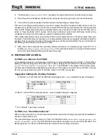
heat 100% outside air is operating with very little outside air, therefore operating at a low fire or cycling. This
allows the cool flue gases from low fire to cool and condense in the chimney.
Over Heating
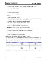
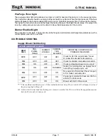
G-TRAC DIAGNOSTIC LIGHTS
HEAT
CALL
PRE-
PURGE
TIMER
BURNER
ENABLED
COMBUSTION
BLOWER
OPERATING CONDITIONS OR
PROBLEM DIAGNOSIS
ON
OFF
ON
RUNNING
CHECK DISCHARGE AND/OR
RESET SENSORS AND
SETPOINT CALIBRATION
OFF
EITHER
ON
EITHER
FAULTY G-TRAC
Rapid Cycling of SA Contacts on G-TRAC Connected to BMS Reset
If a problem exists with the supply air fan rapid cycling during the first start up of the day and the G-TRAC is
connected to a BMS system, there can be some interference. During the off cycle the warm air in the space
may vent back to the unit keeping the discharge air sensor warmer than the internal set-point
(EG: set at 65°F)
.
When the unit is turned on in the morning, the BMS reset would be at zero VDC or 4 Ma at “+ and –“ on the
G-TRAC terminals. It is therefore demanding a 65°F air discharge temperature. As the temperature in the
discharge plenum was warmer then 65°F, the G-TRAC would not call for heat, the fan will start in 34 seconds.
As soon as the fan starts, a current transformer,
(supplied and installed by others)
to prove our fan is running,
sends a signal to the BMS panel. This proves that the unit is now on, which in turn allows the BMS to ramp its
signal to 10VDC to the + and - terminals of the G-TRAC
(because the space temperature was cool from the
unoccupied cycle the night before)
.
This of course results in a call for heat, and cycles the fan off in order for the heat exchanger to warm up.
Voltage to + and - would then go to O VDC, again resulting in no call for heat and the cycle will then repeat.
Note that some DDC or BMS panels
must
have a positive proof of fan operating before reset voltage is
ramped up.
Installing a relay in parallel with the day/night terminal can rectify this problem. Use a VTM time delay and the
DPDT relay contacts
(such as a Honeywell R8222)
. This will lock out the BMS signal for minimum of 3 minutes.
The 3 minutes is required to give the G-TRAC an opportunity to get into its normal operating mode
.
G-TRAC not responding to BMS signal
Refer to the section on BMS above and Section X.
Flame Failure Lockouts
The G-TRAC does not have direct control of the flame supervision. That is usually the task of a Fireye M
Series II Flame Supervision Relay. For most problems refer to the Fireye
(or other flame supervision device)
instructions. The following are a couple of items not covered on their manual.
1. If the combustion air damper is open when the burner starts, it can blow out the pilot flame as it tries to
light. Ensure that the spring used to close the damper is operating correctly. The spring is usually found
behind the gas valve and is attached to the gas valves damper linkage.
(A few units do not have a spring,
they have a counter-weight)
.
2. A very quick interruption of the power can cause a flame failure. The length of time of power failure is less
then ½ second but longer then 1/1000 of a second.
3. A situation that allows for a flame to continue to burn after a heat call is complete, and if that flame is
impinging on the flame rod, can lead to a flame failure if another heat call is made while the flame signal
still exists. We call this a residual flame and it is possible due to the quantity of gas in the main manifold
Summary of Contents for G-TRAC 1.1
Page 23: ...IOM 24 Page i March 1999 R1...

