A
G-TRAC MANUAL
IOM-24
Page 2
March 1999 R1
The flame relay
(external to the G-TRAC)
energizes the ignition transformer and pilot solenoid valve.
When the pilot is established, the flame relay will power the main gas valve and shut off the spark.
The G-TRAC and its associated controls maintain the discharge air temperature.
If the rise in discharge air temperature at low fire is greater than that required to satisfy the set-point, it is
necessary to cycle the burner on and off. The normal G-TRAC will likely cycle at about one minute intervals
and at a 20ºF-temperature swing when a low temperature rise is required. At extra cost the G-TRAC can be
tuned to "high sensitivity" which causes more burner cycling but gives better discharge control during
conditions when only a small increase is needed in discharge temperatures.
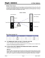
When higher temperature rise is required the G-TRAC will modulate the size of the flame rather than cycle
the burner. Note that burner cycling may occur in temperatures where theory suggests modulation should be
possible. This is caused by the mass of the heat exchanger, the time heat transfers to the air and the time for
the discharge temperature control device to react.
After a heat call is complete the combustion blower will remain in a "maintain purge” mode for 7 to 15
minutes
(depending on jumper selection noted later)
. If the combustion blower is running it will allow a heat
call to start immediately without going through pre-purge.
IV. TEMPERATURE CONTROL
G-TRAC as a Slave to the CTRAC
In this application there is no temperature control sensor or set point attached to the G-TRAC. The G-TRAC’s
ability to control the firing rate is done with a 0 to 10 VDC volt signal from a CTRAC2.1 terminals "HD and B",
(0 to 8.5 VDC on the CTRAC2 version terminal "HT and B")
. The CTRAC2.1 is the master control of the system.
G-TRAC heat call light will be activated when about a 4.5 VDC signal is received from the CTRAC. Terminal
HT to B are connected to D and W of G-TRAC. Refer to C-TRAC manual also.
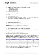
Suggested Settings Re Hunting Problems
C-TRAC2.1 with G-TRAC with TE 6000-960 discharge sensor – may modulate through 20 degrees.
Set C-TRAC Pots
Set G-TRAC Pots
P3 = 6 min. as high as 9
P6 = 5 ***
P11 = 2
P5 = 2
P6 = 4
P8 = 4
C-TRAC2.1 with G-TRAC and hyper sensor – may modulate whtough 10 degrees.
Set C-TRAC Pots
Set G-TRAC Pots
P3 = 6 min. as high as 9
P5 = 2
P6 = 5 ***
P6 = 4
P11 = 2
P8 = 4
*** On C-TRAC2.1 pot 6 does not exist.
G-TRAC as a “Stand Alone Device”
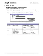
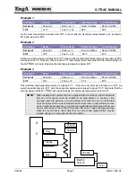
Either the internal set point or an external set point will be used as the discharge set point. Most installations
will use an external set point.
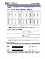
The usual discharge set-point control is a Penn TE 6100-960 control
(which is both a set point and sensor, but
only the set point half is wired)
. The TE 6100-960 set-point device requires a cover such as T4000-264S. The
discharge sensor is a Penn TE 6000-960 sensor located in the discharge air stream.
Summary of Contents for G-TRAC 1.1
Page 23: ...IOM 24 Page i March 1999 R1...

