background image

A


G-TRAC MANUAL 


IOM-24 

Page 5 

March 1999 R1


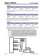
Example 1 

Discharge 

Room 

Room Reset 

High Discharge 

Low Discharge 

Set point 

Set-point 

Ratio 

(Pot 2)


Room Call Max 

Room Call Min 

70ºF 

72°F 

Pos 3 = 

14 

84°F 

56°F 

As the room temperature deviates from 72ºF it can modify the discharge temperatures up to as high as 
84ºF and as low as 56ºF. 

Example 2 

Discharge 

Room  

Room Reset  

High Discharge 

Low Discharge 

Set point 

Set-point 

Ratio 

(pot 2)


Room Call Max 

Room Call Min 

55ºF 

72°F 

Pos 3 = + 14 

 69°F 

41°F 

As the room temperature deviates from 72°F it can modify the discharge temperature up to as high as 69°F 
and as low as 41°F. Note you cannot reach a 72° room temperature. Also note that the internal design of 
the 

G-TRAC

 will resist dropping the discharge temperature below 52°F. 

Example 3 

Discharge 

Room 

Room Reset 

High Discharge 

Low Discharge 

Set point 

Set-point 

Ratio 

(pot 2)


Room Call Max 

Room Call Min 

63ºF 

72°F 

Pos 4 + 18 

81°F 

45°F 

This will allow discharge temperature as high as 81°F.  If the room set point were turned up to 76°F we 
would reset discharge to 81°F until the space temperature was raised to about 76°F. Also note that the 
internal design of the 

G-TRAC

 will resist dropping the discharge temperature below 52°F. 

NOTE

When dealing with systems that are equipped with room reset controls be aware 

that any room sensor must be located in an area where it is sensing a true 
average space temperature. A room reset that is located in a hot or cool area that 
does not represent the room temperature will create room comfort problems. Also 
do not locate the reset sensor in an area that is affected by discharge air from any 
duct or other device. The G-TRAC terminals "RR and +" need to be jumped when 
when the room reset is used. Note that on some wiring diagrams this may be 
jumped during one mode and inactive in another. 


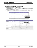
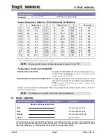
TE6000

TE6000 

Grey 

Orange 

Blue 

Built in 

TE6100


TE6000 

Violet 

Summary of Contents for G-TRAC 1.1

Page 1: ...D OFFICE AND FACTORY CANADIAN EASTERN FACTORY 1401 HASTINGS CRES SE CALGARY ALBERTA T2G 4C8 Ph 403 287 4774 Fx 888 364 2727 32050 W 83rd STREET DESOTO KANSAS 66018 Ph 913 583 3181 Fx 913 583 1406 1175...

Page 2: ...ns and Resistance Values 3 Sensor Resistance Chart for TE 6100 960 and TE 6000 960 4 Temperature Can Be Controlled By 4 VI RESET CONTROL 4 Example 1 5 Example 2 5 Example 3 5 Multiple Room Sensors 6 R...

Page 3: ...Firing 12 Low Heat Burner Firing 12 Unit Short of Temperature Rise 12 Over Delivering Air 13 Inlet Gas Pressure Low or Burner Rumbles 13 Regulator Manifold Pressure Low or Slow to Respond 13 Gas Valve...

Page 4: ...R1 ESTIMATED POT SETTINGS Use for situations where design values not available 16 Combustion Set Up 17 High Fire Combustion Set Up 17 Low Fire Combustion Set Up 17 Mid Fire Range Combustion Set Up 17...

Page 5: ...who is familiar with the control Tampering may misalign the control operation resulting in poor combustion and or poor temperature control or calibration III SIMPLIFIED OPERATION 24 V power to termina...

Page 6: ...later If the combustion blower is running it will allow a heat call to start immediately without going through pre purge IV TEMPERATURE CONTROL G TRAC as a Slave to the CTRAC In this application ther...

Page 7: ...0 85 F and often remote mounted If the TE 6100 960 is used as a set point S to SP must not be jumpered and the TE 6100 must be wired TE 6100 Wires CTRAC2 1 Terminals Violet not used sensor Blue U Oran...

Page 8: ...ature Can Be Controlled By DISCHARGE AIR CONTROL Consists of TE6000 960 duct sensor and set point often TE 6000 960 wired as above or use the internal set point pot 4 with a jumper on S to SP DISCHARG...

Page 9: ...point Ratio pot 2 Room Call Max Room Call Min 63 F 72 F Pos 4 18 81 F 45 F This will allow discharge temperature as high as 81 F If the room set point were turned up to 76 F we would reset discharge...

Page 10: ...Q and U To force a G TRAC to low fire substitute a 1000 ohm resistor for the discharge sensor and adjust the set point pot to a point that just turns the heat call light on VIII G TRAC DISCHARGE TEMPE...

Page 11: ...arge temperature It should be wired to terminals Q and U Adjust pot 1 until the heat light just shuts off This places the G TRAC in its dead band area Return the control to normal Assuming the control...

Page 12: ...ls Z and X and measure the resistance on them Reconnect the wires Compare the reading with the TE 6000 resistance chart in this document Adjust the room reset set point dial to the same value as relat...

Page 13: ...gh to drive the calculated set point below the controls setting It can also result in SA SA contacts cycling and damage the supply air motor or contactor If this is a problem 1 Disconnect all grounds...

Page 14: ...4 20 MA BMS System Position 5 75 1 40 on 0 10 VDC BMS System P8 BURNER ON OFF CONTROL BAND This sets the points at which the burner cycles on and off There is no delay off Setting this control low in...

Page 15: ...TROUBLE SHOOTING Supply Blower Not Starting G TRAC DIAGNOSTIC LIGHTS HEAT CALL PRE PURGE TIMER BURNER ENABLE COMBUS TION BLOWER OPERATING CONDITIONS OR PROBLEM DIAGNOSIS OFF OFF OFF OFF Check for 24 V...

Page 16: ...ints resets and calibration OFF ON OFF RUNNING There has been a short heat call Check for intermittent wiring electrical noise intermittent sensors set points or rapidly changing BMS Signals Shielded...

Page 17: ...cludes the main regulator and the line is not adequately sized an erratic inlet pressure will result and cause improper combustion and also burner pulsating problems Some SJ unit manifolds have RV app...

Page 18: ...f in order for the heat exchanger to warm up Voltage to and would then go to O VDC again resulting in no call for heat and the cycle will then repeat Note that some DDC or BMS panels must have a posit...

Page 19: ...pilot orifice and the depth of the pilot stub past the burner retention plate is very important see sketch below F A poor ground path can contribute to flame failure problems If this is suspected a g...

Page 20: ...lows a maintain purge time of 12 minutes plus or minus 2 minutes ESTIMATED POT SETTINGS Use for situations where design values not available If the old G TRAC is available there was a sticker inside t...

Page 21: ...inlet damper Low Fire Combustion Set Up Remove Q209 used in above step Attach G TRAC wiring from terminals RBW to gas valve Adjust discharge temperature pot or control to just bring heat light on Aft...

Page 22: ...r not calling for heat Supply fan should come on within 34 sec Yes No Normal operation If heat light comes on within 2 min of fan starting fan may shut off while burner prepares for pre purge Pre purg...

Page 23: ...IOM 24 Page i March 1999 R1...

Reviews: