A
RUVG
MANUAL
15 of 35
June 14
COAXIAL
VENTING
‐
COMBUSTION
Indoor
Category
III
Horizontal
Venting
Pressures
in
Category
III
venting
systems
are
positive
and
therefore
care
must
be
taken
to
avoid
flue
products
entering
any
occupied
space.
Use
only
vent
materials
and
components
provided.
The
venting
and
combustion
air
are
integrated
as
a
co
‐
axial
system
with
the
vent
pipe
at
the
center
and
combustion
air
surrounding
the
vent
pipe.
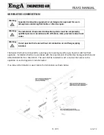
The
total
length
of
vent
pipe
must
not
exceed
4
ft.
(1220mm).
No
elbows
shall
be
used.
Use
the
combination
Vent
Cap
/
Combustion
Air
intake
provided.
Mount
level.
The
vent
terminal
must
be
located
at
least
1
ft.
(305mm)
above
grade,
or
in
snow
areas,
at
least
3
ft.
(1m)
above
snow
line
to
prevent
blockage.
The
vent
terminal
must
be
installed
with
a
minimum
horizontal
clearance
of
4
ft.
(1.2m)
from
electric
meters,
gas
meters,
regulators
or
relief
equipment
(see
following
drawing).
PARALLEL
VENTING
‐
COMBUSTION
The
following
table
indicates
the
maximum
equivalent
length
of
the
various
sizes
of
vent
and
combustion
air
for
each
furnace
model.
Equivalent
length
equals
the
total
length
of
straight
pipe,
plus
10
ft
(3m)
for
each
90°
elbow
and
5
ft
(1.5m)
for
each
45°
elbow.
Maximum
Equivalent
Feet
Vent
Diameter
Combustion
Air
Diameter
Btuh
3”
4”
4”
5”
50,000
100
‐
100
‐
60,000
100
‐
100
‐
70,000
100
‐
100
‐
80,000
‐
100
‐
100
90,000
‐
100
‐
100
100,000
‐
100
‐
100
120,000
‐
100
‐
100
140,000
‐
100
‐
100
160,000
‐
100
‐
100
This
manual
describes
two
options
for
separated
combustion
systems:
RUVG
1220mm
MAX
4 FEET
ATTACH SECURELY TO
WALL WITH SUITABLE
FASTENERS

