background image

A


RUVG 

MANUAL 


16 of 35 

June 14 


Side


Wall


Vent


Vertical


Vent


COMBUSTION


AIR


DUCT


Each


separated


combustion


XE


heater


shall


be


equipped


with


its


own


combustion


air


supply.


It


must


not


connect


to


any


other


air


intake


systems.


Use


single


wall


pipe


constructed


of


minimum


24ga


galvanized


steel


or


a


material


or


equal


durability


and


corrosion


resistance.


Single


wall


combustion


air


duct


may


be


externally


insulated,


as


required.


Each


slip


joint


shall


be


secured


with


corrosion


resistant


screws


or


rivets,


and


sealed


with


an


adhesive


silicon


sealant


and/or


aluminum


tape.


For


horizontal


combustion


air


systems


longer


than


5


ft


(1.5m)


the


piping


must


be


supported


every


3


ft


(1m).


VENTING


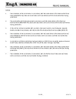
Each


heater


must


have


its


own


vent


system,


and


must


not


be


connected


to


other


venting


systems


or


chimney.


Use


‘C’


Vent.


All


joints


must


be


secured


with


corrosion


resistant


screws


or


rivet,


and


sealed


with


sealant


and/or


aluminum


tape


rated


to


500°F


(290°C).


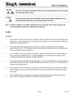
Warning:


Do


not


use


PVC,


ABS


or


any


other


non

metallic


pipe


for


venting.


Any


run


of


single


wall


vent


pipe


passing


through


an


unheated


space


should


be


insulated


with


insulation


rated


for


at


least


550°F


(280°C)


to


prevent


condensing.


In


cases


where


condensing


is


expected,


install


a


Tee


at


the


bottom


of


the


vertical


section,


with


a


drain


for


condensate.


Horizontal


lengths


of


the


vent


system


must


be


installed


and


sloped


(2%)


to


prevent


the


accumulation


of


condensate.


Maintain


a


minimum


of


6”


(150mm)


clearance


from


any


combustible


material.


Do


not


install


dampers


or


other


restrictive


devices


in


the


flue


vent


pipe.


Summary of Contents for RUVG SERIES

Page 1: ...EASTERN FACTORY 1401 HASTINGS CRES SE CALGARY ALBERTA T2G 4C8 Ph 403 287 2590 Fx 403 243 5059 Parts Fax 888 364 2727 32050 W 83rd STREET DESOTO KANSAS 66018 Ph 913 583 3181 Fx 913 583 1406 1175 TWINN...

Page 2: ...Category III Horizontal Venting 15 SEPARATED COMBUSTION 14 COMBUSTION AIR DUCT 16 FLUE GAS VENTING 16 PIPING ELECTRICAL OR CONTROL SERVICE CONNECTIONS 19 ELECTRICAL INSTALLATION 19 Recommended 24V Fie...

Page 3: ...NUAL 3 of 35 June 14 FILTERS 33 CONTROLS 33 CONTROL ENCLOSURE VENTILATION 33 OUTDOOR AIR INTAKES MIXING SECTIONS AND DAMPERS 33 COILS 34 START UP RECORD 35 Airtex Manufacturing Partnership All rights...

Page 4: ...nal service manager SAFETY PRECAUTIONS Read understand and follow the complete manual before beginning the installation including all safety precautions and warnings WARNING FIRE OR EXPLOSION HAZARD F...

Page 5: ...a possible threat of flue gas spillage into the building Warning This unit is connected to high voltages Electrical shock or death could occur if instructions are not followed This equipment contains...

Page 6: ...ies express or implied ENGINEERED AIR specifically disclaims any implied warranty of merchantability and or fitness for purpose Under no circumstances shall ENGINEERED AIR be liable to nor be required...

Page 7: ...k for damage Inspect protective covers for punctures or other signs that there may be internal damage Remove protective covers and check for internal damage Replace covers if the unit is not being ass...

Page 8: ...dian Electrical Code Part 1 C S A Standard C22 1 Provincial and Local Codes and in accordance with the local authorities having jurisdiction 3 The installation of this unit shall be in accordance with...

Page 9: ...National Electrical Code ANSI NFPA 70 4 The installation of this unit shall be in accordance with the latest edition of the National Fuel Gas Code ANSI Z223 1 NFPA 54 State and Local Codes and in acc...

Page 10: ...cal Code For Safety and Service the minimum clearances must be observed Minimum clearances also provide adequate combustion air supply LIFTING Engineered Air units are constructed on a structural stee...

Page 11: ...an and compressor vibration isolators Tie down bolts straps and blocks on tilt equipped heat pipes and enthalpy desiccant wheels if supplied Indirect fired heat exchangers may be supported with wood f...

Page 12: ...as lines shall not interfere with unit access The gas line connection at the heater shall have an approved drip leg with screwed cap 7 A minimum 1 8 inch NPT plugged tapping accessible for test gauge...

Page 13: ...rs or other restrictive devices in the flue vent pipe Vent terminations shall be in accordance with the requirements of the authorities having jurisdiction The vent shall be installed in such a manner...

Page 14: ...local codes Warning Do not operate this heater without all combustion air and flue gas piping installed The heater shall not be connected to a venting system serving any other gas liquid or solid fuel...

Page 15: ...reas at least 3 ft 1m above snow line to prevent blockage The vent terminal must be installed with a minimum horizontal clearance of 4 ft 1 2m from electric meters gas meters regulators or relief equi...

Page 16: ...1m VENTING Each heater must have its own vent system and must not be connected to other venting systems or chimney Use C Vent All joints must be secured with corrosion resistant screws or rivet and se...

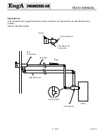
Page 17: ...gineered Air supplied concentric vent terminations are approved for use with RUVG furnace models Refer to the sketch below RUVG Tee with Drain Combustion air Vent pipe Vent Termination Slope Vent Conn...

Page 18: ...be installed at the termination point of the vertical vent system The vent in this arrangement is category 1 B Vent is acceptable Installer may seal joints as required Refer to the sketch below RUVG T...

Page 19: ...1 and to the approval of the authorities having jurisdiction THE FLOOR OF THE UNIT HAS BEEN MADE WATER RESISTANT DO NOT CUT OR DRILL HOLES IN THE FLOOR OR USE PENETRATING FASTENERS Field wiring diagra...

Page 20: ...WG Notes 1 The field wiring load depends on the actual load on a particular control circuit the field wiring is connected to Refer to the internal wiring diagram of the unit 2 The table above is based...

Page 21: ...rants you must comply with all local government safety and environmental laws DRAIN TRAPS Each drain connection requires a separate drain trap supplied and installed by the contractor For a trap to wo...

Page 22: ...EAT TRANSFER FLUIDS The coil s provided have been selected for use with a specific heat transfer fluid as shown on the Submittal Record Use of other fluids will result in different performance and can...

Page 23: ...heck all bearings drive and fan set screws for tightness 5 Turn disconnect switch ON control switch is still off and check the supply voltage Voltage must be within 10 of rating plate If not contact t...

Page 24: ...ir and return air dampers are fully open when the dampers are at a 45 angle when fully stroked This provides optimum mixing of the air streams for this damper arrangement b Angle mixing damper Angle m...

Page 25: ...air volume being delivered matches the unit rating plate Failure to perform a proper air balance can cause injury or death damage to the equipment property damage system operational problems or be a...

Page 26: ...7 If bubble rate is less than noted in the table remove the 6mm tube reconnect the outlet pressure tap plug 8 Energize the control system and open upstream manual gas valve 9 After testing check all...

Page 27: ...ow Operation with airflow less than specified can damage the heat exchanger 4 Do not re start burner when the heat exchanger is a very hot b full of gas 5 Do not start burner unless the supply fan blo...

Page 28: ...flame ignition control used 21 On the initial start up the first ignition trial may be unsuccessful due to need to purge air from manifold at start up If the gas fails to ignite or the flame is not s...

Page 29: ...rush or vacuum affected areas 2 Poorly defined substantially yellow flames or flames that appear lazy indicate poor air supply to burners or excessive burner input Verify gas supply type and manifold...

Page 30: ...off long periods of time the first ignition trial may be unsuccessful due to need to purge air from manifold at start up 8 If the ignition control has locked out clear the lockout by turning the serv...

Page 31: ...h or any other indoor air quality issues If mold or biological growth is present determine and fix the cause Properly remove and dispose of the contamination Properly clean and sanitize the affected a...

Page 32: ...heat exchanger draft inducer vent system operating controls and wiring should be determined Check for obvious signs of deterioration accumulation of dirt and debris and any heat or water related dama...

Page 33: ...water and re install These filters do not require an oil adhesive B Pleated Throwaway and or Replaceable Media Cartridge Bag Replacement filters can be obtained from any Engineered Air representative...

Page 34: ...be cleaned using a low pressure water spray and a brush Coil fins are easily damaged Do not use high pressure steam or water to clean coils it will permanently damage the coil When using cleaning addi...

Page 35: ...on correct Amperage measurement A Gas line supply pressure Off w c High fire w c Manifold gas pressure at high fire w c All field wiring is complete and installed as per the wiring diagram All control...

Reviews: