XF
Rev: 7, 2008-10-14
Page 9
5 INSTALLATION
5.1 Tunnel
installation
IMPORTANT:
Please read the entire instructions carefully before starting the installation.
DANGER!
•
The installation of the thruster(s) must not be carried out in a
confined space where combustible or explosive gases could be
present.
•
The manufacturer assumes no liability whatsoever for the
installation of the propeller tunnel and its attaining parts. Qualified
craftsmen must carry out the work, and responsibility for the
installation rests entirely in the hands of the installer.
IMPORTANT!
Use only an original XF-tunnel, made of fabric glass fibre reinforced
polyester. Smooth in-/outside surface.
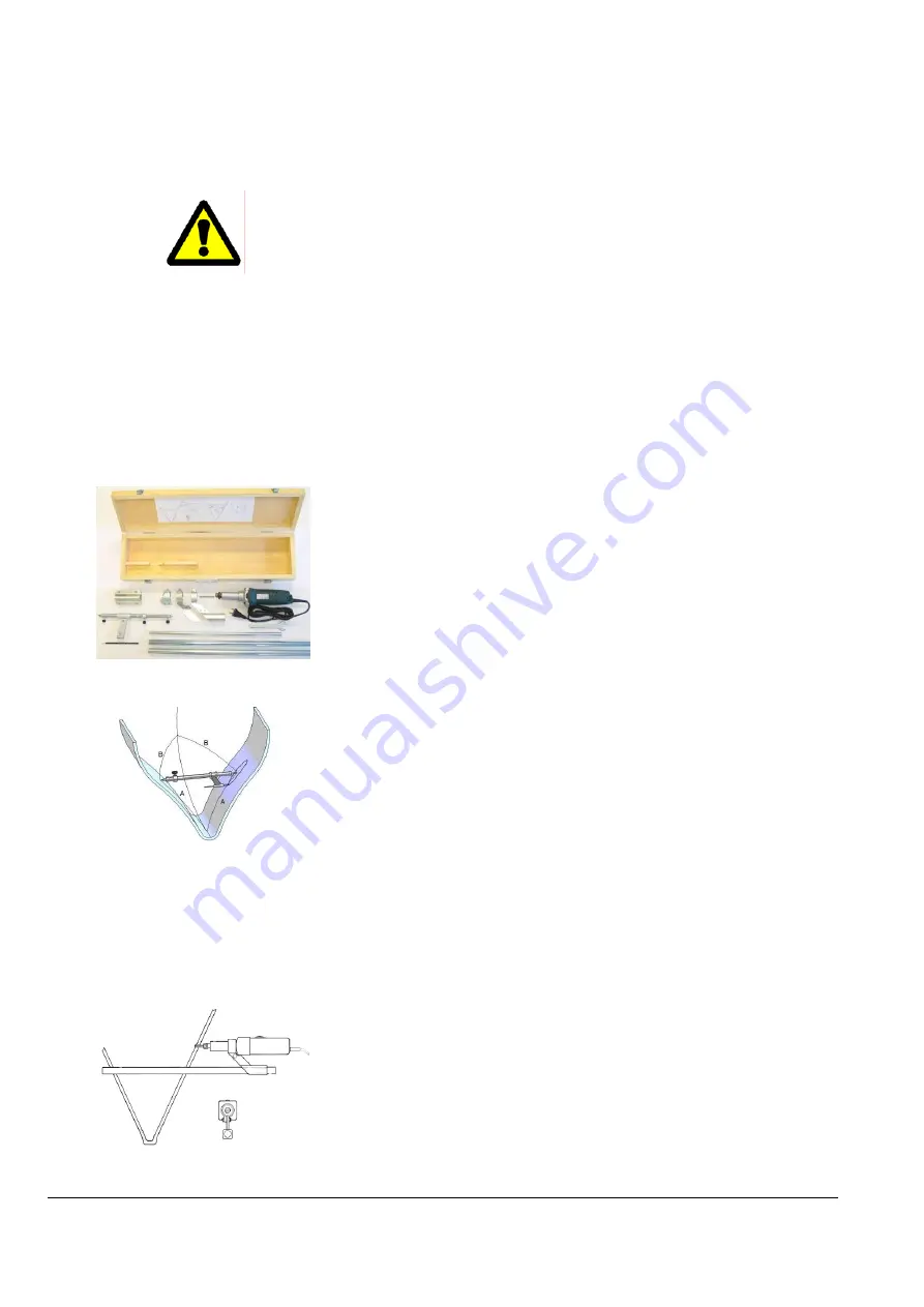
5.1.1
Drilling tool kit
Makes the tunnel installation very efficient and shortens the installation
time considerably.
Consists of:
Compass for easily locating the tunnel centre spot.
Electric straight grinder including centre rods for cutting the holes in the
hull.
Adapters for all thruster dimensions.
For more information ask your dealer or contact Engbo AS directly.
5.1.2
Choosing and marking the location
Select a suitable position for the bow thruster.
For the best result, make sure that the bow thruster is located as far
forward and as low in the hull as possible. To prevent air being drawn into
the tunnel, the upper part of the tunnel should be at least its diameter
below the surface.
Use an appropriate drawing instrument (refer to your dealer regarding
availability of drawing/cutting tools) to mark the point at which the hole for
the bow thruster tunnel is to be inserted.
Mark out the hole in its entirety on the inside of the hull so as to ascertain
the optimum position for the tunnel.
NB:
Make sure that the tunnel is mounted as transverse in the boat as
possible. After having located the centre spots, check both sides
according to selected reference spots in the hull.
5.1.3 Cutting
holes
The installation process can begin once the location of the tunnel has
been marked.
NB:
Do not cut complete circles at first. Small “ears” should be left at the
top and bottom of the circle in order to support the tool during the
operation. A file can then be used to remove the “ears” once both holes
are complete.
Summary of Contents for XForce Series
Page 24: ...XF Rev 5 2008 10 06 Side 24 6 11 Elektriske kobling skjemaer 6 11 1 XForce 20 ...
Page 25: ...XF Rev 5 2008 10 06 Side 25 6 11 2 XForce 40 60 75 90 130 ...
Page 32: ......
Page 56: ...XF Rev 7 2008 10 14 Page 24 7 10 Wiring diagrams 7 10 1 XForce 20 ...
Page 57: ...XF Rev 7 2008 10 14 Page 25 7 10 2 XForce 40 60 75 90 130 ...
Page 64: ......


