XF
Rev: 7, 2008-10-14
Page 18
Fastening the propeller
Use a piece of wood to prevent the propeller rotating while fastening the lock
nut.
Apply bottom coating
All wet parts in the tunnel must be covered with bottom coating.
NB: Ensure that the installation has no leaks when the boat is set afloat.
7 ELECTRICAL
CONNECTIONS
IMPORTANT:
•
Professional qualified craftsmen must carry out the electrical work, and responsibility for
the installation rests entirely in the hands of the installer.
•
Failure to adhere to these requirements will result in the loss of guarantee coverage.
WARNING:
•
The electric power must be turned off during installation.
•
The minimum requirements stated below with reference to battery capacity, cable length
and cable diameter must be adhered to in order to avoid reduced performance and
operational malfunction.
Battery capacity:
Refer to XForce Thruster requirements 7.9.
Recommended main switch:
•
XF 20 and XF 40: Part no. 12-00050
•
XF 60, XF 75, XF 90 and XF 130: Part no: 12-00087
WARNING:
•
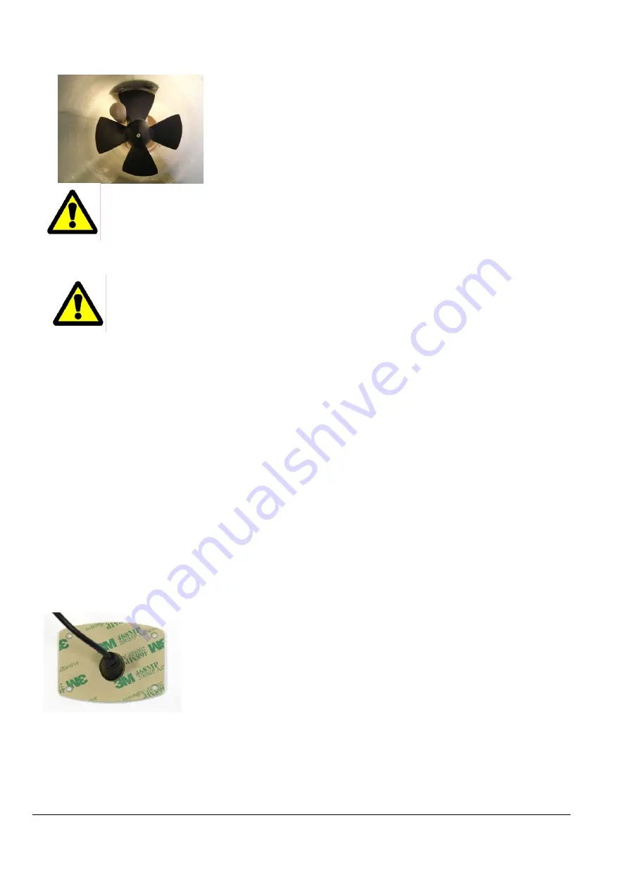
Mind your fingers when testing the propeller!
•
Ensure that no objects are in the tunnel before testing!
•
Make sure that the battery is fully charged before testing.
•
The thruster must only be operated in water.
•
Do not remove belt cover when power is connected
NB:
All cables between the motor control unit and the motor should be kept as short as possible
for optimum performance.
7.1 Touch panel installation
•
Decide where to place the panel.
•
Drill a Ø 15 mm hole.
•
Thread the panel cable trough the hole. Clean the surface.
•
Remove the covering paper on the back of the panel and stick the panel onto
the surface. The holes in the panel corners may be used to fasten the panel
with screws if needed. Tighten with care.
NB:
For optimum appearance, be particular about lining up the panel before sticking it
on.
Summary of Contents for XForce Series
Page 24: ...XF Rev 5 2008 10 06 Side 24 6 11 Elektriske kobling skjemaer 6 11 1 XForce 20 ...
Page 25: ...XF Rev 5 2008 10 06 Side 25 6 11 2 XForce 40 60 75 90 130 ...
Page 32: ......
Page 56: ...XF Rev 7 2008 10 14 Page 24 7 10 Wiring diagrams 7 10 1 XForce 20 ...
Page 57: ...XF Rev 7 2008 10 14 Page 25 7 10 2 XForce 40 60 75 90 130 ...
Page 64: ......


