XF
Rev: 7, 2008-10-14
Page 22
WARNING:
•
To avoid overheating, all connections between the power cable and
components
must
be copper to copper (or copper to brass).
No washers of
any kind
shall be mounted between the power cable lug and the copper
bar/component.
7.7 Fuse
connections
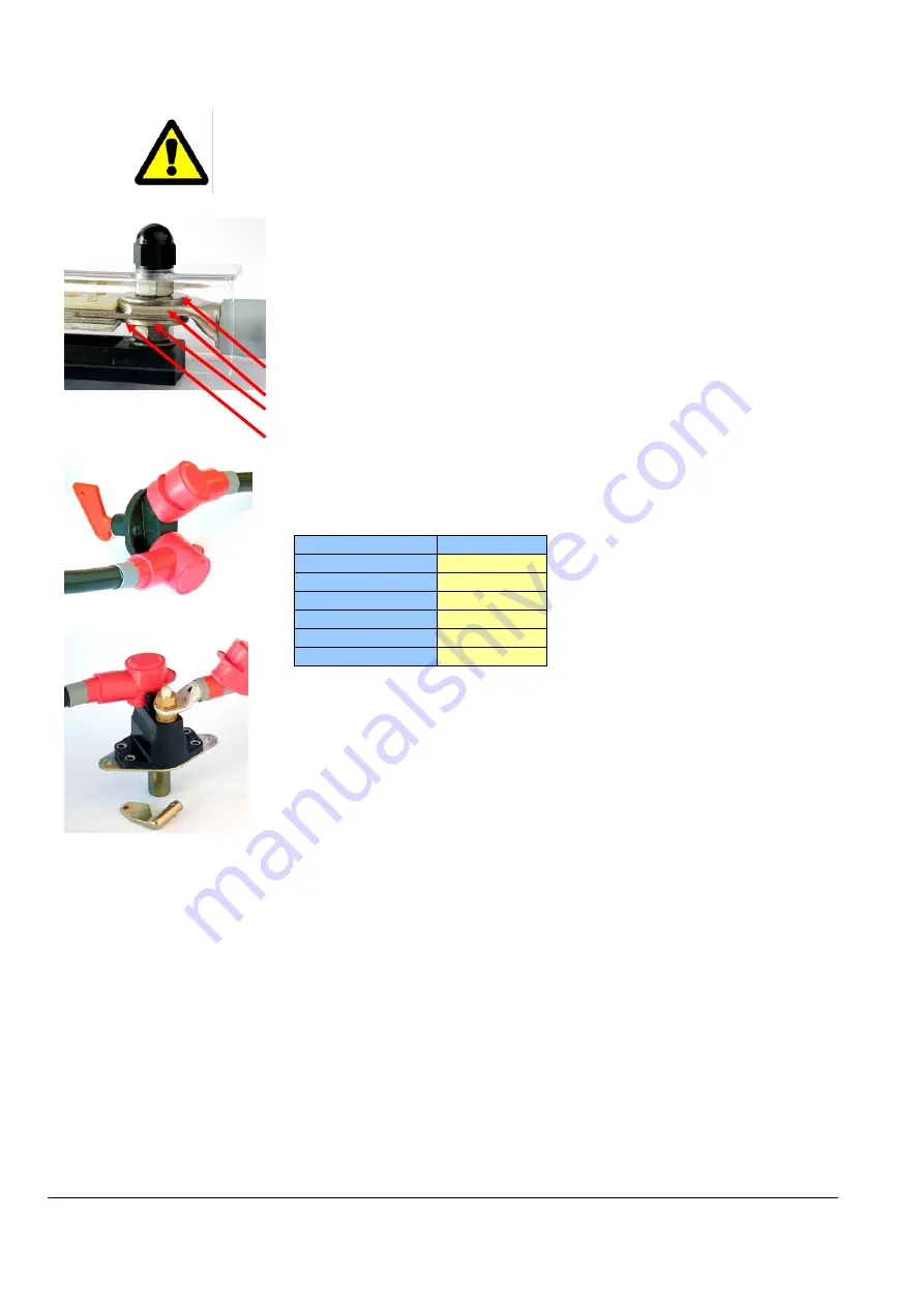
The picture shows the correct power cable connection to the fuse terminal. Note that
the fuse is mounted directly under the power cable lug without any washer in
between. There are supporting washers on each side. (Use large washers with large
cable lug.)
Recommended torque:
20Nm (M8 A4)
Plastic nuts to be mounted on top of plastic cover
•
Supporting
washer
•
Cable
shoe
•
Fuse
•
Supporting
washer
7.8 Recommended main switch
Main switch 12-00050
Thruster model
Part no.
XF 20
12-00050
XF 40
12-00050
XF 60
12-00087
XF 75
12-00087
XF 90
12-00087
XF 130
12-00087
Main switch 12-00087
7.8.1 Main
switch
terminal
The main switch terminal must be isolated as shown in the left-hand picture, i.e. by
using rubber caps or plastic nuts.
Summary of Contents for XForce Series
Page 24: ...XF Rev 5 2008 10 06 Side 24 6 11 Elektriske kobling skjemaer 6 11 1 XForce 20 ...
Page 25: ...XF Rev 5 2008 10 06 Side 25 6 11 2 XForce 40 60 75 90 130 ...
Page 32: ......
Page 56: ...XF Rev 7 2008 10 14 Page 24 7 10 Wiring diagrams 7 10 1 XForce 20 ...
Page 57: ...XF Rev 7 2008 10 14 Page 25 7 10 2 XForce 40 60 75 90 130 ...
Page 64: ......


