XF
Rev: 7, 2008-10-14
Page 26
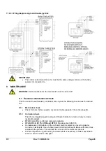
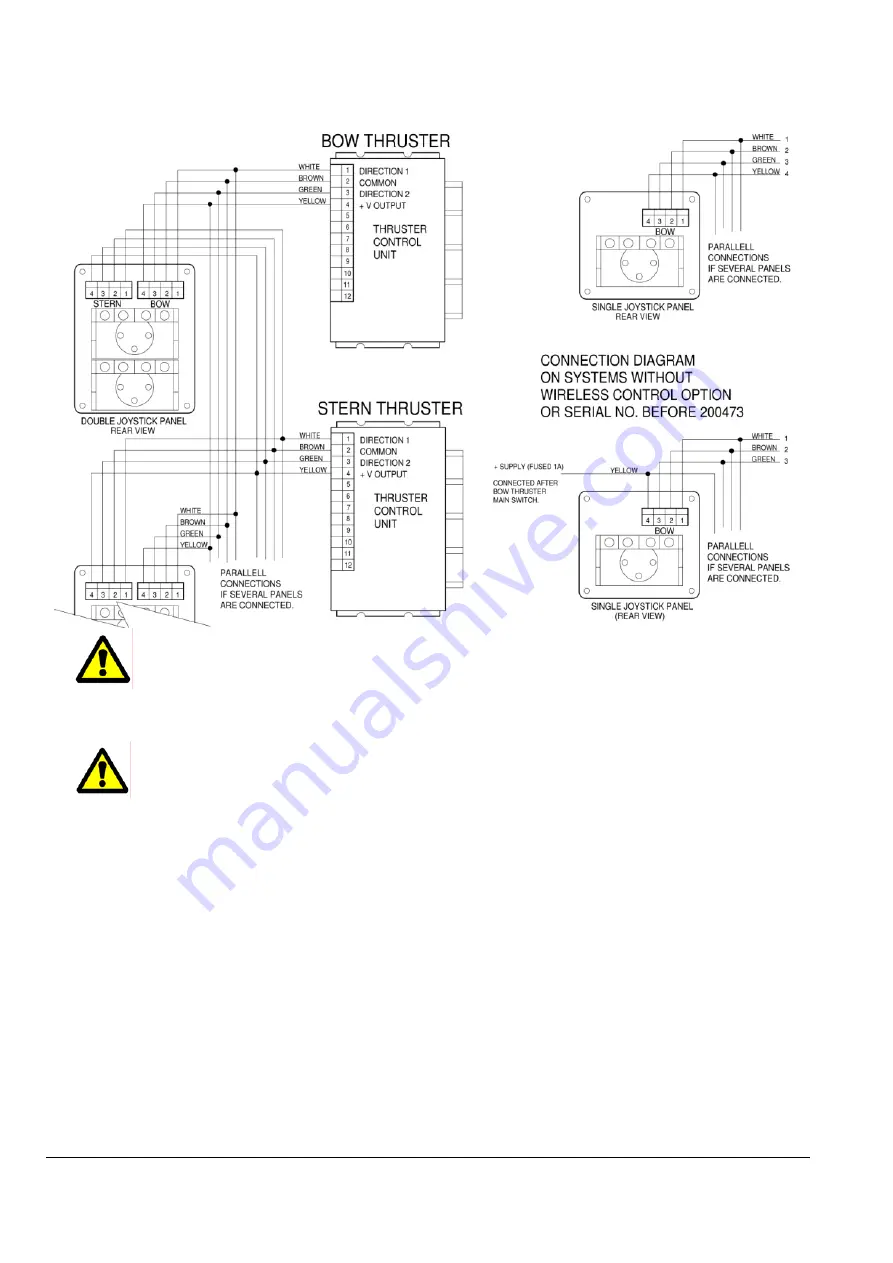
7.10.3 Wiring diagram single and double joystick
IMPORTANT!
•
The control unit and electric motor must be the same voltage version as the battery
system it is connected to.
8 MAINTENANCE
WARNING:
Before maintenance the main switch must be turned off.
8.1 Seasonal
maintenance/check
Prior to use before each season, or at least once a year, the following checks must be carried
out:
8.1.1 Mechanical
check
•
Check for loose bolts, supports, covers and cable supports. Check the propeller.
8.1.2 Corrosion
check
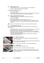
The XForce integrated gearhousing and thruster bracket are made of very corrosion
resistant
materials:
•
XF 20:
Glass fibre reinforced composite material.
•
XF 40, XF 60, XF 75, XF 90 and XF130:
Stainless steel AISI 316.
•
An inadequate configuration of the on board electric system can result in galvanic
corrosion, electrolysis. Use of shore power combined with earth failure will some times
accelerate the process. This will lead to corrosion of the metal components.
•
Periodic inspection of gearhousing and metal parts is necessary to detect and initiate
action to avoid corrosion damages.
Summary of Contents for XForce Series
Page 24: ...XF Rev 5 2008 10 06 Side 24 6 11 Elektriske kobling skjemaer 6 11 1 XForce 20 ...
Page 25: ...XF Rev 5 2008 10 06 Side 25 6 11 2 XForce 40 60 75 90 130 ...
Page 32: ......
Page 56: ...XF Rev 7 2008 10 14 Page 24 7 10 Wiring diagrams 7 10 1 XForce 20 ...
Page 57: ...XF Rev 7 2008 10 14 Page 25 7 10 2 XForce 40 60 75 90 130 ...
Page 64: ......


