4 Installation
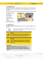
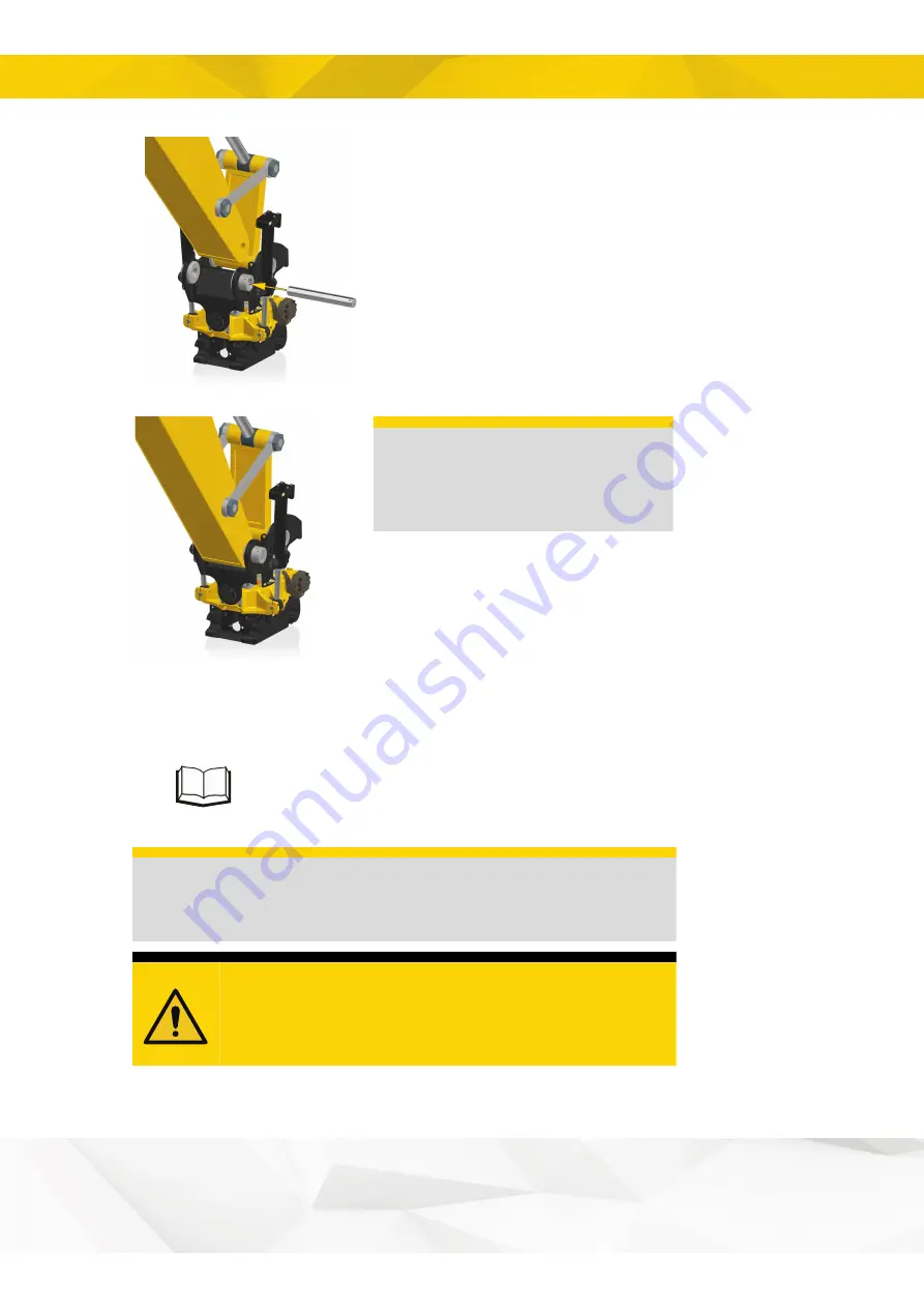
Figure 9.
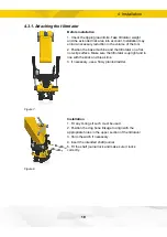
6. Align the break link such that it corresponds to the
holes in the upper section of the tiltrotator/rotator.
7. Lower the stick carefully; make sure that no shear
forces occur.
8. Shim the width if necessary.
9. Apply plenty of grease in the cavity and bushings.
IMPORTANT
Fill the bushings and the cavity
in the stick with grease. Central
lubrication only provides top-ups.
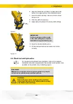
Figure 10.
10. Insert the intended shaft journal.
11. Fit the shaft journal lock and make sure it locks
correctly.
4.4. Electrical and hydraulics
For electrical and hydraulic hose installation, refer to the separate
installation instructions supplied with the selected control system. Also
available on the website or by contacting engcon.
IMPORTANT
Maintenance and repair of the electrical system may only be
carried out by professionally qualified persons.
WARNING
Switch off power when working on the electrical
system and remove any live objects before starting
work Risk of personal injury.
20

