background image

5   Operation

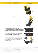
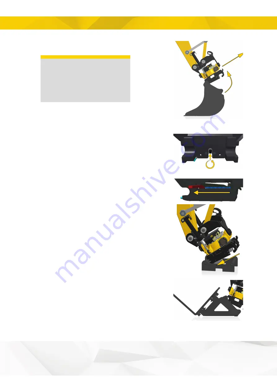
5. The locking bolts are now in the open position and the

tool is free. Carefully raise the tiltrotator from the tool.

IMPORTANT

The machine may only be

operated with the quick hitch

lock switch in the activated

position when connecting and

disconnecting tools.

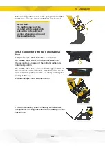
5.9.3. Connecting the tool, mechanical

lock

1. Open the quick hitch lock with a suitable tool
On models with a screw, turn it anti-clockwise until

the locking bolts engage and the indicator rod is in its

outermost position.
On models with a lever, use an extension pipe and move

the lever to its end position. The Indicator rod will then be

in its outermost position and the lock clamp will keep the

locking bolts open.
2. Move the quick hitch towards the tool.

To avoid overloading when connecting the pallet forks,

the quick hitch locking pins must be turned away from the

forklift tines.

30

Summary of Contents for EC204

Page 1: ...User manual TILTROTATOR EC204 EC206 EC209 EC214 EC219 EC226 EC233 Article 9000113 Version 1 20 Original Instructions...

Page 2: ...he market leader in tiltrotators and tools for excavators We represent innovation knowledge and experience and we develop our products with a focus on the customer s needs Please visit our website for...

Page 3: ...iew 12 3 4 HS and SW quick hitch with sensor 13 3 4 1 Overview 14 3 5 EC Oil 15 3 6 ePS C2C 16 3 6 1 Overview 16 4 Installation 4 1 Oil 17 4 2 Identification 18 4 3 Mechanical 18 4 3 1 Attaching the t...

Page 4: ...3 Special maintenance 39 6 3 1 EC Oil 39 6 4 Lubrication every 8 operating hours 40 6 4 1 Tiltrotator lubrication 41 6 4 2 Greasing the quick hitch 42 6 4 3 Lubrication integrated grab GR10 GR20 43 6...

Page 5: ...9 Technical data 9 1 Tiltrotator 57 9 2 Integrated grab cassette 59 9 3 Load holding valve 60 10 Glossary 10 1 Designations 61 10 2 Tiltrotator overview 62 11 Service 11 1 Service schedule 63 11 2 Se...

Page 6: ...rmation in a safe manner and such that it is always available 1 2 Scrapping and recycling engcon makes constant efforts to reduce its environmental impact engcon s products comprise at least 99 per ce...

Page 7: ...ing temperature 30 to 50 C Temperature range during storage 30 to 50 C 1 4 Warranty All customers receive a 2 year warranty on tiltrotators delivered after 1 January 2018 We encourage you to register...

Page 8: ...006 42 EC The following standards and directives have also been applied and complies with EMC Directive 2014 30 EU SS EN ISO 12100 2010 SS EN 474 1 2006 A5 2018 and SS EN 474 5 2006 A3 2013 SS ISO 130...

Page 9: ...1 Introduction 1 6 2 Type certification for lifting hook The following certification is valid for tiltrotators supplied with a lifting hook 9...

Page 10: ...will occur if the regulation is not followed Risk of personal injury or death WARNING Indicates that an accident may occur if the regulation is not followed Risk of personal injury or death CAUTION I...

Page 11: ...onnection of tools to the machine quick hitch and or the quick hitch beneath the tiltrotator It has a double mechanical lock to prevent the tool coming loose from the hitch even if some part of the lo...

Page 12: ...7 Figure 1 Position Description 1 Power supply 2 Alarm indication 3 Sensor machine hitch hook 4 Sensor machine hitch ejector 5 Sensor quick hitch hook 6 Sensor quick hitch ejector 7 Warning lamp Table...

Page 13: ...he tool s locking cylinder is open as the primary safety purpose of the quick hitch is to protect personnel nearby The operator must inform personnel concerned what the alarms mean WARNING Stop work i...

Page 14: ...and function 3 4 1 Overview EC 1 3 2 4 Figure 2 Position Description 1 Power supply 2 Alarm indication 3 Indication for open quick hitch 4 Warning lamp Table 2 For indications see section 7 2 1 Indica...

Page 15: ...nt tool changes It provides the ability to switch hydraulic tools without leaving the cab The system is designed for maximum reliability in harsh environments It is a fully hydraulic system that handl...

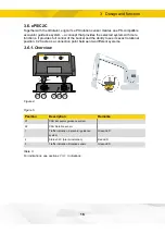
Page 16: ...t and the ability to see its exact rotational position C2C acts as a connection point between two different systems 3 6 1 Overview X1 1 2 X2 3 Figure 4 Figure 5 Position Description Remarks X1 CAN Exc...

Page 17: ...ct on safety Risk of personal injury and damage to property For welding contact your dealer or engcon Nordic AB WARNING Beware of moving parts A lack of awareness may lead to crush injuries Risk of pe...

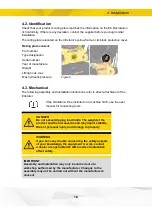
Page 18: ...installation instructions refer to direct attachment of the tiltrotator If the tiltrotator will be installed on a machine hitch use the user manual for connecting tools DANGER Do not exceed tipping lo...

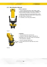
Page 19: ...tiltrotator on a flat non slip surface Make sure the tiltrotator is upright and in line with the stick and break link Figure 7 3 If necessary use a firmly planted ladder Installation 1 Fit any O ring...

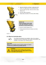
Page 20: ...Figure 10 10 Insert the intended shaft journal 11 Fit the shaft journal lock and make sure it locks correctly 4 4 Electrical and hydraulics For electrical and hydraulic hose installation refer to the...

Page 21: ...e in the operator s cab without obscuring operator visibility WARNING Replace damaged or illegible signs and decals before using the machine Risk of personal injury and damage to property 2 Carry out...

Page 22: ...tools it is intended for See additional information in the separate user manual for each tool WARNING Take care when handling long objects Take dynamic load and the extended risk area into account Ris...

Page 23: ...olding valve on the boom stick and an overload warning when using a lifting hook on the tiltrotator Risk of personal injury and damage to property 5 3 Integrated grab The grab is not designed for lift...

Page 24: ...or slow moving short operations In some cases it can cause the worm gear to overheat Prolonged rotation as with an auger should be avoided IMPORTANT Avoid rotation for extended periods it can cause th...

Page 25: ...DC2 control system for machines with double acting hydraulic circuit The engcon control system allows simultaneous operation of all functions Refer to separate user manual supplied on delivery Also a...

Page 26: ...Separate engcon locking system User manual is available for download on the website or through direct contact with engcon 5 9 Changing tools The following instructions concern general operation of the...

Page 27: ...oned such that the shaft with the EC Oil block is located closest to the base machine If the tool is positioned correctly the block will be visible on the left side of the shaft as seen from the cab P...

Page 28: ...tivate the hydraulics to operate the locking bolts IMPORTANT Always pressurise the tiltrotator to activate the locking cylinder after changing tools 9 Check that the quick hitch lock function engages...

Page 29: ...Activate the hydraulics and the locking bolts 4 The locking cylinders are activated and open position is reached when the indicator rod is visible Q Safe The sound and light warning signals are activ...

Page 30: ...ck hitch lock with a suitable tool On models with a screw turn it anti clockwise until the locking bolts engage and the indicator rod is in its outermost position On models with a lever use an extensi...

Page 31: ...kwise until the locking bolts are retracted and the indicator rod is in its innermost position On models with a lever the lock closes automatically when the adaptor axle forces the lock clamp up 6 Che...

Page 32: ...dels with a lever use an extension pipe and move the lever to its end position The Indicator rod will then be in its outermost position and the lock clamp will keep the locking bolts open In this posi...

Page 33: ...the quick hitch and the tool for minimum play Check that minimum locking wedge engagement is not below the minimum value Quick hitch S30 S80 Quick hitch S1 S3 Figure 16 Figure 17 Quick hitch A max S30...

Page 34: ...on Quick hitch RF40 90 PUP Quick hitch ECPUP Figure 18 Figure 19 Quick hitch A max PUP40 90 14mm Table 6 Quick hitch A max ECPUP45 2mm ECPUP50 5mm ECPUP60 22mm ECPUP65 25mm ECPUP70 25mm ECPUP80 30mm T...

Page 35: ...5 Operation Quick hitch CW10 45 Quick hitch HS Figure 20 Figure 21 Quick hitch A max CW10 45 A B 0 75 Table 8 Quick hitch A max HS08 0 till 14mm HS10 0 to 5mm HS20 21 25 10 till 5mm Table 9 35...

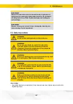
Page 36: ...per section 11 1 Service schedule Complete the service record section 11 2 Service record following each service DANGER Check the attachment points regularly and be alert for the formation of cracks R...

Page 37: ...ydraulic system Use the necessary protective equipment Pressurised hydraulic oil can penetrate the skin Risk of personal injury WARNING Beware of moving parts A lack of awareness may lead to crush inj...

Page 38: ...working That the quick hitch lock buzzer works this check only applies to integrated locks otherwise refer to the base machine s or relevant supplier s user manual that no grease leakage is present o...

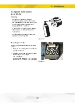
Page 39: ...rease leakage occurs despite cleaning we recommend face seal replacement Clean electrical connectors daily and spray with water repellent Figure 22 Bildtext Replacing face seals Applies to hydraulic c...

Page 40: ...efilling a certain amount of spillage may occur between the body and the hitch s ring Blockage in one grease channel will entail blockage of the entire lubrication system For troubleshooting contact y...

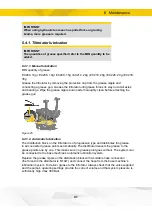
Page 41: ...before attaching the grease gun Figure 25 6 4 1 2 Automatic lubrication The distribution block on the tiltrotator is of progressive type and distributes the grease to all connected grease points autom...

Page 42: ...rly that new grease is supplied to the tiltrotator 6 4 2 Greasing the quick hitch Grease quantity 3 4 pump strokes per nipple Grease nipples on both sides applies to all examples The arrows show the l...

Page 43: ...ease quantity 3 4 pump strokes per nipple The arrows show the location of the grease nipples Figure 30 6 4 4 Lubrication integrated grab GR20RR Grease quantity 3 4 pump strokes per nipple The arrows s...

Page 44: ...Make sure that the upper section is pushed against the base machine by e g wedging a screwdriver between the body and the upper section 2 Undo the tilt axial washer s two bolts 3 Shim the upper secti...

Page 45: ...st firm level ground Figure 33 Remove the protective cover 6 Insert the hex socket into the hole making sure it connects with the worm wheel 7 Mount the dial indicator with the magnetic base and zero...

Page 46: ...l gauge 5 Use the crowbar to move the quick hitch to the right and read off the clock Figure 37 Remove the motor Value Remarks 0 12mm Adjustment required 0 12 0 25 mm Correct rotational play 0 25 mm A...

Page 47: ...ioned to cope with major shear loads and torsional loads For reasons of strength it is essential that certain fasteners be torque tightened Bolts and threaded holes must be thoroughly clean and the th...

Page 48: ...tity Torque Screw cap M12 12 9 8 136 Nm Quick hitch M16 12 9 12 333 Nm Yoke bracket M16 12 9 8 333 Nm Tilt axle M16 12 9 14 333 Nm Clamping half M10 12 9 8 79 Nm Hydraulic motor M12 12 9 2 136 Nm Tabl...

Page 49: ...9 Nm Hydraulic motor M12 12 9 2 136 Nm Table 15 EC233 Fastener Dimension Quality Quantity Torque Screw cap M12 12 9 12 136 Nm Quick hitch M20 12 9 20 649 Nm Yoke bracket M16 12 9 8 333 Nm Tilt axle M2...

Page 50: ...2 1 flash _ _ _ CAN time out Applies to QSC 2 flashes _ _ _ Short circuit power to sensor in EC Applies to SS0 SS9 without QSC and QSC during start 3 flashes _ _ _ Short circuit power to sensor in RF...

Page 51: ...quick hitch underneath tiltrotator 6 1 flash _ _ _ Tiltrotator removed Applies to DC2 Constant light Connected tool Sensor ejector for quick hitch underneath tiltrotator 7 Flashing white and intermit...

Page 52: ...circuit power to sensor in RF Applies when starting up the system 2 flashes _ _ _ Short circuit power to sensor in EC Applies when starting up the system Inactive No fault 3 Constant light Not applic...

Page 53: ...hing CAN communication with the unit connected to X1 3 Off No power supply 3 Constant light No communication in X2 3 Flashing CAN communication with the unit connected to X2 2 Off No fault or no power...

Page 54: ...injury and damage to property 8 1 Decal disposition 8 1 1 Control systems 9 and 10 For decals refer to separate user manual supplied on delivery 8 2 Warning decals The decals are usually placed to the...

Page 55: ...000338 WARNING Risk of injury Make sure locking cylinder is in its maximum extended position before removing locking hook 9000338 B Figure 43 Warning decal on locking cylinder 8 2 3 Symbol legend Impo...

Page 56: ...ave room for rotating tilting and sideways moving tools Risk area 3 metres Crushing hazard from moving parts Never exceed the base machine s approved tipping load Warning rotating tool Warning lateral...

Page 57: ...33 000 Max tensile stress kNm 28 45 74 126 186 270 340 Max bucket width mm 1 000 1 200 1 300 1 600 1 700 2 000 2 200 Max hydraulic pressure MPa 22 22 22 22 22 22 25 Rec hydraulic flow DC2 ss10 l min...

Page 58: ...ength D mm 463 500 561 665 737 760 878 Construction height E mm from 310 from 380 from 425 from 457 from 480 from 500 from 673 Swivel channel extra function number of ports 2 4 4 4 4 4 4 Swivel channe...

Page 59: ...grab width A mm 350 610 820 950 1 080 820 Width B mm 200 270 350 440 380 Length C mm 585 760 910 980 Clamping force tip tip at 21 MPa kg 1 654 1 497 2 234 1 956 1 750 Max load kg 1 000 1 500 2 000 2...

Page 60: ...4 EC206 Torque Nm 4 700 rotation right 5 000 rotation right 7 000 rotation right Torque Nm 3 500 rotation left 4 000 rotation left 6 000 rotation left Description EC209 EC214 EC219 EC226 EC233 Torque...

Page 61: ...is equipped with ePS ECxxR e g EC219R Rotator no tilt function ECxxU e g EC219U Tiltrotator without the valve block and swivel ECxxW e g EC219W Tiltrotator equipped with an extra wide tilt upper secti...

Page 62: ...lubrication 9 Tilt axle 10 Shim set tilt axle 11 Cylinder axle 12 Clamping half 13 Hydraulic motor 14 QS Q safe Sensor Option 15 EC Oil block H Option 16 Locking cylinder 17 Integrated grab cassette 1...

Page 63: ...ongoing checks performed by operator See section 6 5 Service every 250 operating hours Every 2000 operating hours 1 year service to be carried out by a specialist Check the product compliance with th...

Page 64: ...note actions performed on the product that this user manual refer to Specify the date of the action what was done and who did it Service partners must also imprint an ASP stamp in the space provided...

Page 65: ...11 Service Date 500 h 250 h 2000 h Remark Action Stamp Signature 65...

Page 66: ...11 Service Date 250 h 2000 h Remark Action Stamp Signature 66...

Page 67: ...11 Service Date 250 h 2000 h Remark Action Stamp Signature 67...

Page 68: ...engcon Uk Ltd 200B Ashchurch Business Centre Tewkesbury GL20 8TD 44 1684 297168 uk engcon com www engcon com...

Reviews: