background image

26

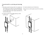
To attach the AP to a wall using wall mounting 
kit.

1. 

Determine where the Access Point to be placed and 
mark locations on a surface for the two mounting holes. 

Use an appropriate drill bit to drill two 8.1mm diagram 

and 26mm depth holes in the markings and hammer the 
bolts into the opening.

2.

  Screw the anchors unto the holes until they are flush 

with the wall.


3.

  Screw the included screws into the anchors.

4.

 Place this Access Point against wall with the mounting 

heads.

1

2

4

3

Summary of Contents for ENS500-AC

Page 1: ...User Manual Business Solutions 11AC Wave2 Outdoor Access Point CPE ENS500 AC ENS500EXT AC ENS610EXT ENS620EXT version 1 1 ...

Page 2: ...2 IMPORTANT To install this Access Point please refer to the Quick Installation Guide included in the product packaging ...

Page 3: ... 41 Realtime 41 Chapter 6 Network 43 Basic IPv4 IPv6 Settings 44 Spanning Tree Protocol Setting 44 Chapter 7 2 4 GHz 5 GHz Wireless 46 WirelessSettings 47 2 4 GHz 5 GHz Wireless Network 48 2 4GHz 5 GHz SSID Profile 50 Wireless Security 51 Wireless MAC Filtering 54 Wireless Advanced 55 Fast Roaming 56 WDS Link Settings 57 Guest Network Settings 58 Chapter 8 Management 58 Management VLAN Settings 60...

Page 4: ...4 Chapter 1 Product Overview ...

Page 5: ... items on Band Steering for intellgent Manage ment Traffic Shaping to control bandwidth per SSID user Secured Guest Network option available The AP is 802 11 ac wave2 a b g n Outdoor Access Point with speeds up to 400 Mbps on 2 4GHz and 867Mbps on 5GHz band It can be configured as an Access Point Client Bridge or WDS AP Station Bridge The AP is an affordable solution which is built in high powered...

Page 6: ...Bridge The AP is an affordable solution which is built in high powered radios and long range settings to replace the ordinary Access Points that do not have the range and reach to connect to a growing number of wirelessusers WithWave2features theAccessPointcould reduce the handling period on client devices and network with more client devices at the same time Meanwhile the beamforming features wil...

Page 7: ...GHz Omni directional Antennas PoE Adapter EPA2410GP 3 pin IEC 320 C6 Power Cord Pole Mount Ring x 1 Wall Mount Screw Set Quick Installation Guide all items must be in package to issue a refund The ENS500 AC package contains the following items Access Point PoE Adapter EPA2406GP 3 pin IEC 320 C6 Power Cord Pole Mount Ring x 1 Wall Mount Screw Set Quick Installation Guide all items must be in packag...

Page 8: ...on 64 128 152 bit WPA WPA2 Personal WPA PSK using TKIP or AES WPA WPA2 Enterprise WPA PSK using TKIP or AES ENS620EXT Standard IEEE802 11 ac wave2 ac a n on 5 GHz IEEE802 11 b g n on 2 4 GHz Antenna 2 x detachable 5 dBi 2 4 GHz Omni directional Antennas 2 x detachable 5 dBi 5 GHz Omni directional Antennas Physical Interface 2 x 10 100 1000 Gigabit Ethernet Ports with PoE support LAN1 Port Propriet...

Page 9: ...ection list Https Support SSH Support QoS Quality of Service Complaint with IEEE 802 11e standard Physical Environment Conditions Operating Temperature 20 C to 60 C 4 F to 140 F Humidity non condensing 90 or less Storage Temperature 30 C to 80 C 22 F to 176 F Humidity non condensing 90 or less ...

Page 10: ... WEP Encryption 64 128 152 bit WPA WPA2 Personal WPA PSK using TKIP or AES WPA WPA2 Enterprise WPA PSK using TKIP or AES ENS610EXT Standard IEEE802 11 ac wave2 ac a n on 5 GHz IEEE802 11 b g n on 2 4 GHz Antenna 2 x detachable 5 dBi 2 4 GHz Omni directional Antennas 2 x detachable 5 dBi 5 GHz Omni directional Antennas Physical Interface 2 x 10 100 1000 Gigabit Ethernet Ports with PoE support LAN1 ...

Page 11: ...nection list Https Support SSH Support QoS Quality of Service Complaint with IEEE 802 11e standard Physical Environment Conditions Operating Temperature 20 C to 60 C 4 F to 140 F Humidity non condensing 90 or less Storage Temperature 30 C to 80 C 22 F to 176 F Humidity non condensing 90 or less ...

Page 12: ...tion Modes Access Point WDS Client Bridge WDS Detail WDS AP WDS Bridge WDS Station Management Auto Channel Selection Multiple SSID 8 SSIDs BSSID SNMP V1 V2c V3 MIB I II Private MIB VLAN Tag VLAN Pass through Clients Statistics Save Configuration as User Default Traffic Shaping per SSID user E Mail Alert RADIUS Accounting Guest Network Control CLI Supported Distance Control Ack Timeout 802 1X Suppl...

Page 13: ...nection list Https Support SSH Support QoS Quality of Service Complaint with IEEE 802 11e standard Physical Environment Conditions Operating Temperature 20 C to 60 C 4 F to 140 F Humidity non condensing 90 or less Storage Temperature 30 C to 80 C 22 F to 176 F Humidity non condensing 90 or less ...

Page 14: ...tics Save Configuration as User Default Traffic Shaping per SSID user E Mail Alert RADIUS Accounting Guest Network Control CLI Supported Distance Control Ack Timeout 802 1X Supplicant CB Mode Multicast Supported Auto Reboot Obey Regulatory Power Security WEP Encryption 64 128 152 bit WPA WPA2 Personal WPA PSK using TKIP or AES WPA WPA2 Enterprise WPA PSK using TKIP or AES ENS500EXT AC Standard IEE...

Page 15: ...nection list Https Support SSH Support QoS Quality of Service Complaint with IEEE 802 11e standard Physical Environment Conditions Operating Temperature 20 C to 60 C 4 F to 140 F Humidity non condensing 90 or less Storage Temperature 30 C to 80 C 22 F to 176 F Humidity non condensing 90 or less ...

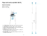
Page 16: ...GHz Antennas Detachable 5 dBi 5 GHz Omni directional 3 LAN Port 1 Proprietary24V PoE Ethernet port for RJ 45 cable 4 LAN Port 2 Ethernet port for RJ 45 cable 5 LED Indicators LED lights for Power LAN Port 1 LAN Port 2 2 4 GHz Connection and 5 GHz Connection 6 Ground Cable 7 Mounting Holes Using the provided hardware the AP can be attached to a wall or pole 1 6 7 2 2 1 5 3 4 1 ...

Page 17: ...onal 2 5 GHz Antennas Detachable 5 dBi 5 GHz Omni directional 3 LAN Port 1 Proprietary24V PoE Ethernet port for RJ 45 cable 4 LAN Port 2 Ethernet port for RJ 45 cable 5 LED Indicators LED lights for Power LAN Port 1 LAN Port 2 2 4 GHz Connection and 5 GHz Connection 6 Mounting Holes Using the provided hardware the AP can be attached to a wall or pole 5 6 2 1 1 3 4 2 ...

Page 18: ... 5 GHz Omni directional Antennas ENS500EXT AC Only 2 LAN Port 1 Proprietary24V PoE Ethernet port for RJ 45 cable 3 LAN Port 2 Ethernet port for RJ 45 cable 4 LED Indicators LED lights for Power LAN Port 1 LAN Port 2 2 4 GHz Connection and 5 GHz Connection 5 Mounting Holes Using the provided hardware the AP can be attached to a wall or pole 1 1 2 3 4 5 ...

Page 19: ...19 Chapter 2 Before You Begin ...

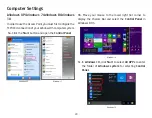
Page 20: ...r system 1a Click the Start button and open the Control Panel 1b Move your mouse to the lower right hot corner to display the Charms Bar and select the Control Panel in Windows 8 OS 1c In Windows 10 click Start to select All APPs to enter the folder of Windows system for selecting Control Panel Computer Settings Windows XP Windows 7 Windows 8 Windows 10 ...

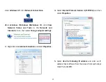
Page 21: ...he Network and Internet section then select Change adapter settings 3 RightclickonLocalAreaConnectionandselectProperties 4 Select Internet Protocol Version 4 TCP IPv4 and then select Properties 5 Select Use the following IP address and enter an IP address that is different from the Access Point and Subnet mask then click OK ...

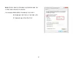
Page 22: ...22 Note Ensure that the IP address and Subnet mask are on the same subnet as the device For example ENH220EXT IP address 192 168 1 1 PCIPaddress 192 168 1 2 192 168 1 255 PC Subnet mask 255 255 255 0 ...

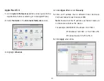
Page 23: ...ion 3 Highlight Ethernet 4 In Configure IPv4 select Manually 5 Enter an IP address that is different from the Access Point and Subnet mask then press OK Note Ensure that the IP address and Subnet mask are on the same subnet as the device For example ENH900EXT IP address 192 168 1 1 PCIPaddress 192 168 1 2 192 168 1 255 PC Subnet mask 255 255 255 0 6 Click Apply when done ...

Page 24: ...l outlet D Connect the second Ethernet cable into the LAN port of the PoE adapter and the other end to the Ethernet port on the computer E Place the pane removed from step A back into the device F Screw on the provided antennas to the top of this device AppliedontheENS500EXT AC ENS610EXT ENS620EXT This diagram depicts the hardware configuration Note The Access Point NOLY supports the included prop...

Page 25: ...25 Mounting the AP Using the provided hardware the AP can be attached to a wall or a pole 1 Wall Mounting Kit Anchors Φ5 5 18 mm Bolts Φ8 25mm 2 Pole Mounting Strap Φ63 5 12 7 mm Bolts Anchors ...

Page 26: ...the two mounting holes Use an appropriate drill bit to drill two 8 1mm diagram and 26mm depth holes in the markings and hammer the bolts into the opening 2 Screw the anchors unto the holes until they are flush with the wall 3 Screw the included screws into the anchors 4 Place this Access Point against wall with the mounting heads 1 2 4 3 ...

Page 27: ...the AP to a pole using the provided pole mounting kit 1 Thread the open end of the pole strap through the two tabs on the Pole Mount Bracket 2 Lock and tighten pole strap to secure pole mount bracket to the pole 1 2 ...

Page 28: ...ld be properly grounded to a viable path for lightning surge to deliver to ground so that is does not go into the building network This AP have a ground lug on the left side of this AP which is applied to attach a proper ground to Attention You must always install an external grounding wire ensure that you have completed grounding before you connect power to the unit ...

Page 29: ...29 Chapter 3 Configuring Your Access Point ...

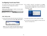
Page 30: ...t Explorer Firefox Safari Chrome and enter the IP Address http 192 168 1 1 Note If you have changed the default LAN IP Address of the AccessPoint ensureyouenterthecorrect IPAddress 2 The default username and password are admin Once you have entered the correct username and password click the Login button to open the web base configuration page The model name will be varied by different models 3 If...

Page 31: ...31 Chapter 4 Building a Wireless Network ...

Page 32: ...utdoor Access Points or Client Premise Equipments CPE Access Point Mode InAccessPointMode APbehaveslikesacentralconnectionforstationsorclientsthatsupportIEEE802 11ac a b g nnetworks The stations and clients must be configured to use the same SSID Service Set Identifier and security password to associate with the AP The AP supports up to eight SSIDs per band at the same time for secure access AP Ac...

Page 33: ...idge mode Since the computers are on the same subnet the Access Point can broadcast to reach all end devices If you use the client bridge mode in this Access Point you can use the AP Detection feature to scan for Access Points within range When you find an Access Point configure this Access Point to use the same SSID and Security Password as the Access Point to associate with it ...

Page 34: ...e capability of their internal high gain directional antennas resulting in a very cost effective solution to expand a company network over a multiple building campus AP Access Point AP Client Bridge ENH202 Client Bridge ENH202 Client Bridge ENH500 Client Bridge Client Client Client Client Client Client Client Client Client Client Client 2 4 GHz 5 GHz 5 GHz 2 4 GHz Switch Switch Internet ...

Page 35: ...S technology In this mode configure the MAC addresses or SSIDs in both Access Points to enlarge the wireless area by enabling WDS Link settings WDS AP mode supports up to four 4 AP MAC addresses and four 4 SSIDs at the same time AP WDS AP AP WDS AP 2 4 GHz 2 4 GHz 5 GHz 5 GHz Client Client Client Client Client Computer Client Computer ...

Page 36: ...shown in the following diagram WDS Bridge Mode can establish up to four 4 to eight 8 WDS links creating a star like network Note WDS Bridge Mode does not act as an Access Point Access Points linked by WDS are using the same frequency channel More Access Points connected together may lower throughput This configuration can be susceptible to generate endless network loops in your network so it is re...

Page 37: ...ation WDS STA mode expands the WDS by receiving a wireless signal service and sharing it through the Ethernet port With WDS STA mode Access Point WDS AP on both 5 GHz or 2 4 GHz Access Point WDS Station Access Point WDS Station ...

Page 38: ...38 Chapter 5 Status ...

Page 39: ...tus link under the Overview menu shows the status information about the current operating mode The Device Information section shows general system information such as Device Name MAC Address Current Time Firmware Version and Management VLAN ID Note VLAN ID is only applicable in Access Point WDS AP or WDS BR mode The Memory Information section shows usage of memory such as Total Available Free Cach...

Page 40: ...tocol STP The Wireless LAN Information 2 4 GHz 5 GHz section shows wireless information such as Operation Mode Frequency andChannel SincethisAccessPointsupports multiple SSIDs information about each SSID the ESSID and security settings are displayed Note Profile Settings are only applicable in Access Point and WDS AP modes The Statistics section shows Mac information such as SSID MAC address RX an...

Page 41: ... GHz 5 GHz WDS Link List Click the connection link under the Overview menu This page displays the current status of the WDS link including WDS Link ID MAC Address Link Status and RSSI Note Only applicable in WDS AP and WDS Bridge modes Realtime The Realtime section contains the following options CPU Loading 3 minutes CPU loading percentage information it displays current loading average loading an...

Page 42: ...and peak time Realtime Connection Pkts Overview on current active network connections It displays UDP and TCP packets information and other connection status UDP connections curve is in blue TCP connection curve is in green others curve is in red Below of chart shows connections source and destination ...

Page 43: ...43 Chapter 6 Network ...

Page 44: ... Primary Secondary DNS The primary secondary DNS address for this device Save Click Save to confirm the changes Spanning Tree Protocol STP Settings This page allows you to modify the Spanning Tree settings Enabling the Spanning Tree protocol will prevent network loops in your LAN network Spanning Tree Status Enables or Disables the Spanning Tree function Default is Disable Hello Time Specifies Bri...

Page 45: ...lay time is the time spent in each of the Listening and Learning states before the Forwarding state is entered This delay is provided so that when a new bridge comes onto a busy network it analyzes data traffic before participating in the network Priority Specifies the Priority Number A smaller number has a greater priority than a larger number Save Click Save to confirm the changes ...

Page 46: ...46 Chapter 7 2 4 GHz 5 GHz Wireless ...

Page 47: ...band capable client devices to network to the 2 4GHz band only if the client devices are not currently associated on 2 4GHz radio in this AP Prefer 5GHz When band steering is configured to Prefer 5GHz mode the AP will steer dual band capable client devices to 5GHz radio when the RSSI value of these client devices on 5GHz radio is more than set one The allowed RSSI value for default setting is 75dB...

Page 48: ...own this list to select wireless broadcasting standard on 2 4GHz and 5GHz frequency bands ChannelHTMode Scrowdownthislisttoselectbandwidth for operating under a frequency band The default channel bandwidth is 20 MHz on 2 4GHz frequency radio and 40 MHz on 5GHz frequency radio Considering the different applications users can decide to implement a channel bandwidthtofulfillrealapplications Thelarger...

Page 49: ...is also lowered RTS CTS Threshold Specifies the threshold package size for RTC CTS A small number causes RTS CTS packets to be sent more often and consumes more bandwidth ClientLimits Limitsthetotalnumberofclientsonthisradio Once setting the ceiling of client numbers the maximum assocaited client devices will be restricted at this number Aggregation Integrate multiple data packets into one packet ...

Page 50: ...n SSID Check this option to hide the SSID from clients If checked the SSID will not appear in the site survey ClientIsolation Clicktheappropriateradiobuttontoenable this function for allowing or preventing communication between client devices VID Specifies the VLAN tag for each profile If your netowrk includes VLANs you can specify a VLAN ID for packets pass through the Access Point with a tag Wir...

Page 51: ...ended Hexadecimal Numbers For advanced users Key Length Select the desired option and ensure that wireless clients use the same setting Your choices are 64 128 and 152 bit password lengths Default Key Select the Key you wish to be the default Transmitted data is ALWAYS encrypted using the Default Key the other Keys are for decryption only You must enter a Key Value for the Default Key Encryption K...

Page 52: ...the Key must be from 8 to 63 characters in length If using HEX format the Key must be 64 HEX characters in length Group Key Update Interval Specifies how often in seconds the Group Key changes The default value is 3600 Setting of WPA Enterprise WPA2 Enterprise Pre Shared Key Encryption Select the WPA encryption type you would like Pleaseensurethatyourwirelessclientsusethesamesettings Radius Server...

Page 53: ...s Accounting Port Enter the port number used for connections to the Radius accounting server Radius Accounting Secret Enter the secret required to connect to the Radius accounting server Interim Accounting Interval Specifies how often in seconds the accounting data sends Note 802 11n does not allow WEP WPA PSK TKIP WPA2 PSK TKIP security mode The connection mode will automatically change from 802 ...

Page 54: ...Disable Wireless MAC Filter Note Only applicable in Access Point and WDS AP modes ACL Mode Determines whether network access is granted or denied to clients whose MAC addresses appear in the MAC address table on this page Your choices are Disabled Deny MAC in the list or Allow MAC in the list MAC Address Enter the MAC address of the wireless client Add Click Add to add the MAC address to the MAC a...

Page 55: ...o enable Wireless Traffic Shaping per SSID Download Limit Specifies the wireless transmission speed used for downloading Upload Limit Specifies the wireless transmission speed used for uploading Per User Check this option to enable wireless traffic shaping per user function This function allow users to limit the maximum download upload bandwidth for each client devices on this SSID Save Click Save...

Page 56: ... Server firstly Users can enable the Fast Roaming and implement the advanced search Please also set the same enterprise Encryption under the same SSID on other Access Points and enable the Fast Roaming When the configuration is realized on different Access Point the mobile client devices can run the voice service and require seamless roaming to prevent delay in conversation from Access Point to Ac...

Page 57: ...cess Points in the WDS network need to use the same Channel and Security settings To create a WDS network please enter the MAC addresses of the Access Points that you want included in the WDS There can be a maximum of four Access Points Note Only applicable in WDS AP and WDS Bridge modes 2 4 GHz 5 GHz WDS Link Settings Security Select None or AES from the drop down list AES Passphrase Enter the Ke...

Page 58: ...s The first IP Address in the range of the addresses by the DHCP server Ending IP Address The last IP Address in the range of addresses assigned by the DHCP server RSSI Threshold AP mode Only RSSI Threshold Enable the RSSI Threshold feature by ensuring that each client is served by at least one Access Point at any time Access Points continuously monitor the connectivity quality of any client in th...

Page 59: ...59 Chapter 8 Management ...

Page 60: ...xt to one another on the LAN Note Only applicable in Access Point and WDS AP modes Management VLAN If your network includes VLANs you can enable Management VLAN ID for packets passing through the Access Point with a tag Save Click Save to confirm the changes or Cancel to cancel and return to previous settings Note If you reconfigure the Management VLAN ID you may lose your connection to this AP Ve...

Page 61: ...tails of the device Location Specifies the location of the device Community Name Read Only Specifies the password for the SNMP community for read only access Community Name Read Write Specifies the password for the SNMP community with read write access Trap Destination Address Specifies the IP address of the computer that will receive the SNMP traps Trap Destination Community Name Specifies the pa...

Page 62: ...ntent securely The Hypertext Transfer Protocol over SSL Secure Socket Layer is a TCP IP protocol used by web servers to transfer and display web content securely Email Alert You can use the Email Alert feature to send messages to the configured email address when particular system events occur Note Do NOT use your personal email address as it can unnecessarily expose your personal email login cred...

Page 63: ...unt that will be used to send emails Password Enter the password for the email account that will be used to send emails SMTP Server Enter the IP address or hostname of the outgoing SMTP server Port Enter the SMTP port number to use for outbound emails ...

Page 64: ...ally Get Date and Time and check whether you wish to enter the IP address of an NTP server or use the default NTP server to have the internal clock set automatically Time Zone Choose a time zone to implement the service for this AP Enable Daylight Saving Check whether daylight savings applies to your area Start Select the day month and time when daylight savings time starts Enable Daylight Saving ...

Page 65: ... can specify how often you wish to reboot the AP Auto Reboot Setting Enables or disables the Auto Reboot function Timer Select the day and enter the time you would like to reboot automatically Save Click Save to apply the changes ...

Page 66: ... Fi scheduler function Wireless Radio Select 2 4 GHz or 5 GHz from the drop down list for the preferred band type SSID Selection Select a SSID from the drop down list Schedule Templates Select a schedule template from the drop down list Day s Place a checkmark in the boxes for the desired days or select the All Week radio button to select all seven days of the week Duration The Start Time is enter...

Page 67: ... address you would like to search Ping Packet Size Enter the packet size of each ping Number of Pings Enter the number of times you wish to ping Start Ping Click Start Ping to begin pinging the target device via IP Traceroute Target Enter the IP address or domain name you wish to trace Start Traceroute Click Start Traceroute to begin the trace route operation Tools ...

Page 68: ...t you would like the test to implement for and in how many intervals IPv4 IPv6 Port This Access Points uses IPv4 5001 and IPv6 5002 port for the speed test Start Click start to implement speed test LED Control Control LED on off for Power LAN interface or 2 4 GHz 5 GHz WLAN interface Power Enables or disables the Power LED indicator LAN Enables or disables the LAN LED indicator WLAN 2 4 GHz Enable...

Page 69: ...69 Device Discovery This page allows you to discover devices from network for Operation Mode IP Address System MAC Address and Firmware version ...

Page 70: ...y box Verify Password Re enter the new password in the Confirm Password entry box for confirmation Apply Click Apply to apply the changes Firmware Upgrade This page allows you to upgrade the firmware of the AP To Perform the Firmware Upgrade 1 Click the Choose File button and navigate the OS file system to the location of the upgrade file 2 Select the upgrade file The name of the file will appear ...

Page 71: ...ou have set the AP incorrectly you can use the Reset button in the Revert to Factory Default Settings section to restore all the configurations of the AP to the original default settings Backup Setting Click Export to save the current configured settings Restore New Setting To restore settings that have been previously backed up click Browse select the file and click Restore Restore to Default Cli...

Page 72: ...user settings you would like to the device s memory for the default settings Restore to User Default Click Restore to restore user settings to the factory standard settings Note1 After setting the current settings as the default you should click the Restore to Default on the web interface for reverting the settings into the factory default instead of pushing the reset button Note2 Please write dow...

Page 73: ...s are deleted from the log When powered down or rebooted the log will be cleared Status Enable Disable this function Log type You may choose one of log types to display logs in the following window The default log types is All Remote Log This page allows you to setup the Remote Log functions for this AP Remote Log Enable Disable this function Log Server IP Address Enter the IP address of the log s...

Page 74: ...ck on Reset to reboot the AP Once you click reset button you will see the options for reboot or restore this AP Reboot the device Click it to reboot this device Restore to Factory Default Click it to reset this device to factory default setting Restore to User Default Click it to reset this device to user default settings For realizing the setting method you may refer page 65 and page 66 ...

Page 75: ...75 Appendix ...

Page 76: ...nician for help FCC Caution this equipment This device complies with Part 15 of the FCC Rules Operation is subject to the following two conditions 1 This device may not cause harmful interference and 2 this device must accept any interference received including interference that may cause undesired operation This transmitter must not be co located or operating in conjunction with any other antenna...

Page 77: ... Datatransmissionequipmentoperating inthe2 4GHzISMbandandusingspreadspectrummodulationtechniques HarmonizedENcoveringessentialrequirementsunderarticle 3 2 of the R TTE Directive EN301893 BroadbandRadioAccessNetworks BRAN 5GHzhighperformanceRLAN HarmonizedENcoveringessentialrequirementsofarticle3 2of the R TTE Directive EN301489 1 ElectromagneticcompatibilityandRadioSpectrumMatters ERM ElectroMagne...

Page 78: ...d at følgende udstyr udstyrets typebetegnelse overholder de væsentlige krav og øvrige relevante krav i direktiv 1999 5 EF Deutsch German Hiermit erklärt Name des Herstellers dass sich das Gerät Gerätetyp in Übereinstimmung mit den grundlegenden Anforderungen und den übrigen einschlägigen Bestimmungen der Richtlinie 1999 5 EG befindet Eesti Estonian Käesolevaga kinnitab tootja nimi name of manufact...

Page 79: ...iumaprovvedimenti oħrajn relevanti li hemm fid Dirrettiva 1999 5 EC Magyar Hungarian Alulírott gyártó neve nyilatkozom hogy a típus megfelel a vonatkozó alapvetõ követelményeknek és az 1999 5 EC irányelv egyéb elõírásainak Polski Polish Niniejszym nazwa producenta oświadcza że nazwa wyrobu jest zgodny z zasadniczymi wymogami oraz pozostałymi stosownymi postanowieniami Dyrektywy 1999 5 EC Português...

Page 80: ...om nearby person in normal operation condition to meet regulatory RF exposure requirement External Antenna Useonlytheantennaswhichhavebeenapprovedbytheapplicant Thenon approvedantenna s mayproduceunwantedspuriousorexcessive RF transmitting power which may lead to the violation of FCC limit and is prohibited Installation Procedure Please refer to user s manual for the detail Warning rules The viola...

Reviews: