background image


5

distance between the telephone and the pacemaker.  Do not 
carry the handset in a breast pocket.  If you have any reason 
to suspect that interference is taking place, turn off your 
handset immediately. 


Product Safety Instructions 

 
1.  Read and understand all instructions. 

2.  Follow all warnings and instructions including those marked on 

the product. 

3.  Changes or modifications to this product not expressively 

approved by the manufacturer will void the warranty and the 
FCC authorization to operate the equipment.  Use only 
manufacturer provided accessories.  

4.  Do not use the telephone near water.  Never spill liquid of any 

kind on this product. 

5.  Unplug the product from the wall telephone jack and power 

outlet before cleaning.  Do not use liquid or aerosol cleaner s.  
Use damp cloth for cleaning. 

6.  Do not place this product on an unstable cart, stand or table.  

The product may fall and cause personal injury or damage to 
the product or other property.  Place the base station and the 
charger on hard, flat surfaces.  

7.  Power Outage: 

In the event of a power outage, your handset charger will not 
recharge the handset battery, and the base station will not 
allow you to make an outgoing call or take an incoming call.  
Both the charger and the base station require electricity for 
operation.  

You should have a telephone that does not require 

electricity available for use during power outage, or have a 
temporary backup power supply.


8.  Slots or openings in the product’s housing are provided for 

ventilation.  These openings must not be blocked or covered.  
Placing the product on a bed, carpeting, or other similar 
surface may block these openings and should be avoided.  
This product should never be placed near or over a radiator or 
heat register, or in a built-in installation unless proper  
ventilation is provided. 

9.  Never push objects of any kind into this product through 

housing slots/openings as they may damage the product, 


6

touch dangerous voltage points or short out parts that could 
result in fire, electric shock, or injury.   

10.  This product should be operated only from the type of power 

source indicated on the marking label.  If you are not sure of 
the type of power supply to your home, consult your dealer or 
local power company. 

11.  Do not overload wall power outlets and extension cords as this 

may result in fire or electric shock. 

12.  To avoid electric shock or burn, do not disassemble this 

product.  Send this product to an authorized service center 
when service or repair work is required.  Call Customer 
Service for locations near you.  Opening or removing covers 
may expose you to dangerous voltages, electrical currents or 
other risks.  Incorrect reassembling of the product may cause 
electric shock when the product is subsequently used. 

13.  Avoid using the product during a storm.  There may be a risk 

of electric shock from lightning.  

14.  Do not place the product where persons can step, trip, or fall 

on the product. 

15.  Do not place conductive objects over or near the antenna. 

16.  Do not use the product to report a gas leak while in the vicinity 

of the leak. 

17.  Do not install the base station or the handset charger near 

microwave ovens, radios, TV sets, speakers, or other 
electrical equipment.  These appliances may cause 
interference to the product or experience interference from the 
product. 

18.  Unplug the base station or the charger adaptor from the wall 

power outlet and refer servicing to an authorized service 
center under the following conditions: 

a.  If liquid had been spilled into the product. 
b.  When the power supply cord or plug is damaged or frayed.  
c.  If the product has been exposed to rain or water. 
d.  If the product does not operate normally by following the 

operating instructions. 

e.  If the product has been dropped or housing has been 

damaged. 

f.  If the product shows a distinct change in performance.  

Battery Safety Instructions 


Summary of Contents for SP-922

Page 1: ...t Features 13 Additional Handset Features 15 Base Illustration 19 Base Features 20 Basic Base Station Features 20 Additional Base Station Features 21 Administrator Features 22 Charger Illustration 23...

Page 2: ...n an emergency a If an emergency occurs dial the emergency phone number Remember if you are in an area where your phone does not have a clear signal from the base it is highly probable that the call m...

Page 3: ...s of any kind into this product through housing slots openings as they may damage the product 6 touch dangerous voltage points or short out parts that could result in fire electric shock or injury 10...

Page 4: ...pt any interference received including interference that may cause undesired operation Privacy of communications may not be ensured when using this phone 8 The term IC before the radio certification n...

Page 5: ...ference We recommend at least 20 feet between the system and other electronic devices b Connect the base station to a power outlet on a circuit separate from that used by the device experiencing inter...

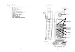
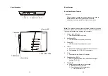
Page 6: ...Handset Short Antenna x 1 f 1700mA Li ion Battery Pack x 2 g Charger x 1 h Charger AC DC Adaptor x 1 i Telephone Cord x 1 j Handset Belt Clip x 1 k User s Manual Warranty Card 12 Handset Illustration...

Page 7: ...le 5 TALK FLASH a Places or answers a telephone or intercom call b Toggles between calls in built in call waiting operations 14 c Sends a Flash signal to phone line to retrieve a dial tone after the c...

Page 8: ...setting this feature please check your PBX system if it can send a reverse signal to hang up the line 9 Call Conferencing a 2 handset and 1 line conferencing b 1 handset and 2 line conferencing 10 DN...

Page 9: ...25 Four keytone type selections 26 Display call time duration for current call during and immediately after the call 27 Text Messaging a Editing Message from a handset users can edit a screen full up...

Page 10: ...le turn clockwise to install turn counterclockwise Improper installation may damage the connector 1 Audio in Jack 3 5 mm Provides MOH Music on Hold 2 Line Status LED s LED lit indicates an active tele...

Page 11: ...res 1 4 channel Auto Attendant a 4 Auto Attendant can be active at the same time in case of 4 simultaneous incoming calls b Allows private paging to a single handset with individual Handset ID or grou...

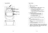
Page 12: ...tery is placed in slot b LED as the spare battery charging indicator 1 Slot is empty and the power is on LED is Green light 2 Charging LED is Orange light 3 Fully Charged LED returns to Green light 4...

Page 13: ...his common phone number the phone company automatically finds a free line In a hunt group the Call Waiting and the Caller ID with Call Waiting or called Type 26 II Caller ID features are unnecessary b...

Page 14: ...search for an available line and dial out If Line Selection option has been enabled the handset will be prompted to select from a list of available lines 2 If all 4 lines are occupied including if som...

Page 15: ...CAST key to end the 11 PA paging to all 11 PApaging to Ext 02 11 PA paging to Ext 12 30 broadcasting Notes 1 You need to continuously press BROADCAST key when doing broadcast The broadcast will be ove...

Page 16: ...ections Default 4 3 Use Up and Down Arrow key to turn up or down the earpiece volume 32 4 The new setting remains effective for all future calls until changed Notes To achieve maximum volume adjust th...

Page 17: ...pre registered with the base station at the factory 2 You need to register the handset with the base station in the following situations a If a handset displays a Handset ID 00 that means it is a new...

Page 18: ...ets de registered by the administrator can still perform 36 intercom to other handsets 4 Obtain a Specific Handset ID a If a particular Handset ID is preferred over sequentially assigned ID the admini...

Page 19: ...n handset Notes If the destination handset does not answer after handset paging timeout the call is routed back to the originating handset 38 3 Way Conferencing 1 While a telephone call is in progress...

Page 20: ...ted by the greeting message to enter a two digit extension number Handset ID or press 0 for operator 3 The greeting message is user programmable The Handset ID that is designated as the operator is al...

Page 21: ...call waiting is separate from the Call Waiting feature available from the local phone company The phone company provided Call Waiting functions on the same phone line while the Call Waiting functions...

Page 22: ...nes are used for different purposes 5 When AA is disabled the line can be dedicated to either an individual Handset ID or a Group ID 6 The operator can be any individual handset or a group it doesn t...

Page 23: ...wait for the cursor to advance or use the Up Down Arrow to move the cursor backward or forward manually Also use Up and Down Arrows to move the cursor to insert to the left of the cursor or delete the...

Page 24: ...own Arrow to scroll through the list i Press OPTION Right soft key for options Press 1 and confirm to erase current record Press 2 to view the arrival date and time of the call Press 3 to edit and sav...

Page 25: ...to save change f Press 6 to change LCD display contrast i Use Up Down Arrow to scroll through values 1 to 16 Pick one that is most suitable to you Default 10 ii Press SAVE Left soft key to save settin...

Page 26: ...e handset is in standby b Press 8 to enter Inbox menu c The LCD displays Message 01 the most recent received message Use Up Down Arrow to view previous messages d Press SAVE Left soft key to return th...

Page 27: ...FCC Rules These limits are designed to provide reasonable protection against harmful interference in a residential installation This equipment generates uses and can radiate radio frequency energy an...

Page 28: ...ess phone when tested for use at the ear is 0 43 W Kg and when worn on the body as described in this user guide is 0 182 W Kg This transmitter must not be co located or operating in conjunction with a...

Reviews: