


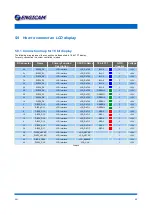
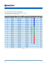


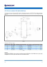


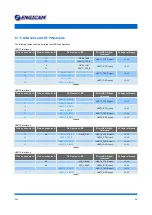
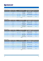
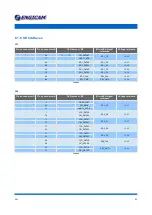
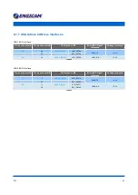
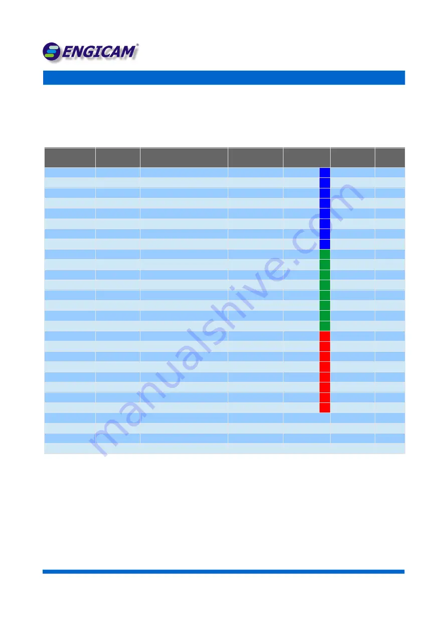
5.9.2 Connection map for 24 bit display
The following map represent the connection mode applied to 24 bit TFT display.
For every connection the colour controlled is joined
B Connector
Name
Primary Function
Description
CPU Pin Name
18 bit TFT
GPIO
Capable
Voltage
26
DISP0_D0
LCD interface
LCD_DAT00
BLU 0
Y
+3,3V
24
DISP0_D1
LCD interface
LCD_DAT01
BLU 1
Y
+3,3V
16
DISP0_D2
LCD interface
LCD_DAT02
BLU 2
Y
+3,3V
18
DISP0_D3
LCD interface
LCD_DAT03
BLU 3
Y
+3,3V
22
DISP0_D4
LCD interface
LCD_DAT04
BLU 4
Y
+3,3V
30
DISP0_D5
LCD interface
LCD_DAT05
BLU 5
Y
+3,3V
28
DISP0_D6
LCD interface
LCD_DAT06
BLU 6
Y
+3,3V
36
DISP0_D7
LCD interface
LCD_DAT07
BLU 7
Y
+3,3V
20
DISP0_D8
LCD interface
LCD_DAT08
GREEN 0
Y
+3,3V
14
DISP0_D9
LCD interface
LCD_DAT09
GREEN 1
Y
+3,3V
2
DISP0_D10
LCD interface
LCD_DAT10
GREEN 2
Y
+3,3V
6
DISP0_D11
LCD interface
LCD_DAT11
GREEN 3
Y
+3,3V
8
DISP0_D12
LCD interface
LCD_DAT12
GREEN 4
Y
+3,3V
10
DISP0_D13
LCD interface
LCD_DAT13
GREEN 5
Y
+3,3V
12
DISP0_D14
LCD interface
LCD_DAT14
GREEN 6
Y
+3,3V
4
DISP0_D15
LCD interface
LCD_DAT15
GREEN 7
Y
+3,3V
32
DISP0_D16
LCD interface
LCD_DAT16
RED 0
Y
+3,3V
34
DISP0_D17
LCD interface
LCD_DAT17
RED 1
Y
+3,3V
39
DISP0_D18
LCD interface
LCD_DAT18
RED 2
Y
+3,3V
49
DISP0_D19
LCD interface
LCD_DAT19
RED 3
Y
+3,3V
1
DISP0_D20
LCD interface
LCD_DAT20
RED 4
Y
+3,3V
3
DISP0_D21
LCD interface
LCD_DAT21
RED 5
Y
+3,3V
47
DISP0_D22
LCD interface
LCD_DAT22
RED 6
Y
+3,3V
51
DISP0_D23
LCD interface
LCD_DAT23
RED 7
Y
+3,3V
38
DISP0_HSYNC
LCD interface
LCD_HSYNC
-
Y
+3,3V
40
DISP0_VSYNC
LCD interface
LCD_VSYNC
-
Y
+3,3V
42
DISP0_DRDY
LCD interface
LCD_ENABLE
-
Y
+3,3V
44
DISP0_CLK
LCD interface
LCD_CLK
-
Y
+3,3V
Table 16
D N :
3 6