001-01-000092 Rev. 000
Page 3 of 5
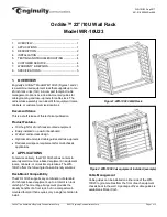
Remove the mounting frame from the wall and drill
pilot holes for each of the marked screw locations.
Before attempting to fasten the mounting frame to the
wall, insert a screw into the top pilot hole on either the
left or right side. Partially thread the screw into the
hole, leaving the screw head approximately 1/4
” from
the surface.
Hold the mounting frame against the wall while resting
the cutout of the bracket on the installed screw. Align
the other five mounting holes and install a screw in
each hole. Tighten all six (6) screws securely.
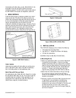
B. Frame grounding
Locate the eight (8) pairs of pre-installed grounding
screws with lock washers on the crossbar of the
frame. The grounding screws are 10-32 x
3/8” on 5/8”
centers.
Install a dual ground lug (customer provided) with
holes on 5/8” centers beneath the included screws
and washers on one pair of grounding holes. Tighten
the screws to fasten the lug to the mounting frame.
The example in Figure 7 illustrates the frame
positioned with grounding screws facing downward.
Connect a ground wire of appropriate gauge to the
ground lug, and attach the other end of the wire to a
bonded ground point, per local procedures for network
equipment.
C. Equipment Installation
Install rack equipment with 23
” hole spacing by
carefully sliding the chassis through the front of the
WR-10U23 and aligning chassis mounting ears with
the threaded holes in the rails of the WR-10U23
frame. Insert and tighten #12-24 machine screws
(customer provided) on each side of the chassis. An
example of a fully populated wall rack is shown in
Figure 2.
Attach ground lugs associated with each equipment
chassis to the threaded ground holes on the WR-
10U23 crossbar as needed.
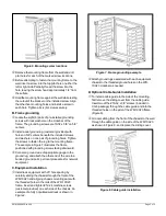
D. Optional Cable Guide Installation
To install a cable guide to the side of the mounting,
first remove the sliding cover from the cable guide.
Insert two of the #10-
32 x 3/8” screws (included in
CG-5 package) through the cable guide and into the
threaded holes on the side of the WR-10U23 frame
(Figure 8).
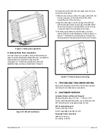
Groom cabling from the front of the chassis to the wall
through the cable guide on the side of the WR-10U23,
as shown in Figure 9, and replace the sliding cover.
Figure 6. Mounting screw locations
Figure 7. Frame grounding example
Figure 8. Cable guide installation

