10/22
AMF 3.1 USER MANUAL
17
N/A
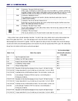
Terminal connection is empty, please do not make any connections.
18
N/A
Terminal connection is empty, please do not make any connections.
19
N/A
Terminal connection is empty, please do not make any connections.
20
OIL PRESURE SEND.
Analog oil pressure sender is to be connected to this terminal. The settings related to this
input can be changed via parameters P084-P144.
21
TEMP SEND.
Analog water temperature sender is to be connected to this terminal. The settings related to
this input can be changed via parameters P147-P203.
22
N/A
Terminal connection is empty, please do not make any connections.
23
CHARGE FAIL INP.
Charge alternator excitation winding is connected to this input. The panel excites the charge
alternator by feeding constant current during cranking. This terminal feeds 120mA in 24V
systems and 200mA in 12V systems. Panel marş sırasında sabit akım basarak şarj
a
ltarnatörüne uyartım vermektedir. Bu çıkıştan 24V sistemlerde 120mA, 12V sistemlerde 200
mA akım basılmaktadır
24
CRANK
Crank solenoid is to be connected to this output.
25
COM 6
The common input of Terminals No 24 and No 26.
Caution: In order to enable the related Terminals to COM 6, this input must NOT
be left empty.
26
FUEL
The fuel or stop solenoid is to be connected to this input. The settings related to this input can
be changed via parameters P017 and P028.
27
COM 7
The common input of Terminals No 28, No 29, No 30 and No31. Can be connected to Battery
- or . Because the digital inputs are bi-directional, when connected to Battery - the
digital inputs are activated on B voltage level and vice versa.
Caution: If a battery connection is NOT made to COM 7 the related digital inputs
will not be operational.
28
AUX INPUT 1
1
st
digital input. Can be configured via parameters P206-P211.
29
AUX INPUT 2
2
nd
digital input. Can be configured via parameters P212-P217.
30
AUX INPUT 3
3
rd
digital input. Can be configured via parameters P218-P223.
31
AUX INPUT 4
4
th
digital input. Can be configured via parameters P224-P229.
32
COM 8
The common input of Terminals No 33, No 34, No 35 and No36. Can be connected to Battery
- or . Because the digital inputs are bi-directional, when connected to Battery - the
digital inputs are activated on B voltage level and vice versa.
Caution: If a battery connection is NOT made to COM 8 the related digital inputs
will not be operational.
33
AUX INPUT 5
5
th
digital input. Can be configured via parameters P230-P235.
34
AUX INPUT 6
6
th
digital input. Can be configured via parameters P236-P241.
35
N/A
Terminal connection is empty, please do not make any connections.
36
N/A
Terminal connection is empty, please do not make any connections.
37
N
Mains Neutral input
38
T
Mains T Phase input (20-500Vac)
39
S
Mains S Phase input (20-500Vac)
40
R
Mains R Phase input (20-500Vac)
41
N
Alternator Neutral input
42
N/A
Terminal connection is empty, please do not make any connections.
43
N/A
Terminal connection is empty, please do not make any connections.
44
U
Alternator U Phase input (20-500Vac)
45
N/A
Terminal connection is empty, please do not make any connections.
46
N/A
Terminal connection is empty, please do not make any connections.
47
N/A
Terminal connection is empty, please do not make any connections.
48
N/A
Terminal connection is empty, please do not make any connections.
49
IR-
R Phase Current Transformer input - terminal (Max. 5A AC)
50
IR+
R Phase Current Transformer input + terminal (Max. 5A AC)

