9/22
AMF 3.1 USER MANUAL
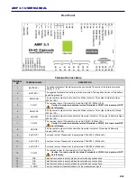
Rear Panel
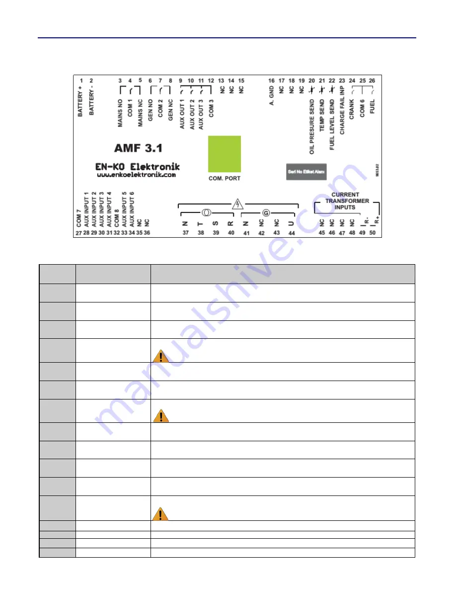
Terminal Connections
TERMINAL
NO
TERMINAL NAME
DESCRIPTION
1
B
The positive terminal of the battery must be connected. The value of the terminal must be
between 9
– 30V.
2
BATTERY -
The negative terminal of the battery must be connected. The negative terminal of the battery
should be grounded.
3
MAINS NO
The dry contact output, which controls the Mains contactor. This output is Normally Open.
(250Vac 10A)
4
COM 1
The common input of Terminals No 3 and No 5 (MCB). (250Vac 10A)
Caution: In order to enable the related Terminals to COM 1, this input must NOT
be left empty.
5
MAINS NC
The dry contact output, which controls the Mains contactor. This output is Normally Closed.
(250Vac 10A)
6
GEN NO
The dry contact output, which controls the Generator contactor. This output is Normally Open.
(250Vac 10A)
7
COM 2
The common input of Terminals No 6 and No 8 (GCB). (250Vac 10A)
Caution: In order to enable the related Terminals to COM 2, this input must NOT
be left empty.
8
GEN NC
The dry contact output, which controls the Generator contactor. This output is Normally
Closed. (250Vac 10A)
9
AUX OUT 1
Functional output. Please refer to parameters P254-P255. (250Vac 6A)
10
AUX OUT 2
Functional output. Please refer to parameters P256-P257. (250Vac 6A)
11
AUX OUT 3
Functional output. Please refer to parameters P258-P259. (250Vac 6A)
12
COM 3
The common output for Terminals No 9, No 10 and No 11.
Caution: In order to enable the related Terminals to COM 3, this input must NOT
be left empty.
13
N/A
Terminal connection is empty, please do not make any connections.
14
N/A
Terminal connection is empty, please do not make any connections.
15
N/A
Terminal connection is empty, please do not make any connections.
16
A. GND
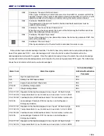
To be connected to Generator chassis for the measurement inputs.

