background image

CCS3100 


User Manual R0.2 


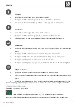
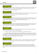
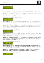
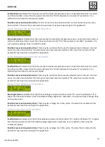
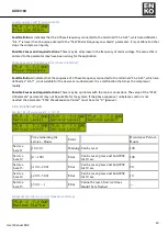
 Shows how much time is left for the oil change service. The duration is set with P100 

Oil Change maintenance parameter among the service times parameters. 


 Shows how much time is left for Air Filter replacement service. The duration is set with 

P101 Air Filter Replacement parameter among the service times parameters. 


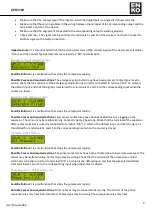
 Shows how much time is left for the Oil Filter replacement service. The duration is set 

with P102 Oil Filter Replacement parameter among the service times parameters. 


 Shows how much time is left for Separator Filter replacement service. The duration is 

set with P103 Separator Filter Replacement parameter among the service times parameters. 


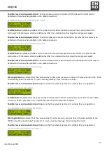
 Shows the total motor running time. 


 Shows the motor's time at load (producing air). 

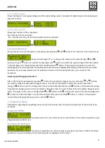
1.4.3.3 Phase Voltages 

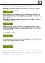
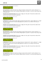
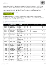
Information regarding the 3-phase voltage and frequency connected to the device is displayed.  


1.4.3.4 Digital I/O 

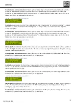
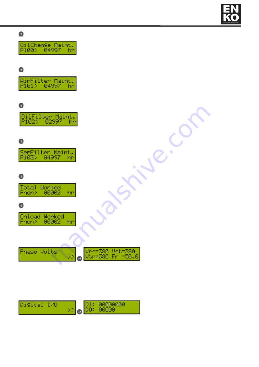
Shows the input and output status of the device. If the value is "0", the corresponding input or output is passive. If it 
is "1", it indicates that the corresponding input or output is active. 
DI: Digital Input 
 DO: Digital Output 


Summary of Contents for CCS 3100

Page 1: ...2021 CCS 3100 COMPRESSOR CONTROL SYSTEM USER MANUAL FATIH DALO LU...

Page 2: ...the fault logs service times pressure temperature and voltages measured by the device input and output states counters related to the compressor through the menu and also adjust the parameters of the...

Page 3: ...the selected parameter enters to the parameter setting screen When pressed on the parameter setting screen saves the set value When pressed on the password entry screen moves the cursor to the next c...

Page 4: ...w Version Indicates the version of the device software BootVer The boot software version of the device After showing the software version for 3 seconds the device shows the company information screen...

Page 5: ...r of total operating hours at the time of alarm occurrence The line at the bottom provides the alarm definition For the alarm detail you see see 2 6 Alarm and Warning Descriptions and solution advices...

Page 6: ...ent parameter among the service times parameters Shows how much time is left for Separator Filter replacement service The duration is set with P103 Separator Filter Replacement parameter among the ser...

Page 7: ...essing and Changing Parameters After confirming the password by pressing button the parameter category menu is accessed or buttons are used to navigate in parameter category menus To access the parame...

Page 8: ...and P031 Preheat on Load time Main Contactor and Delta Contactor are active Idle Run IDLE The device runs the compressor in idle mode The solenoid valve is passive and the compressor does not produce...

Page 9: ...er and it waits for the time entered to the P026 Auto Waiting Delay parameter to expire The device runs the compressor in idle state and run in idle state for a period that is bigger than the value en...

Page 10: ...parator Filter Separator Filter Fault Definition It is a malfunction that stops the compressor rapidly Possible Causes and required actions Filter sensor contact may have been activated due to a clogg...

Page 11: ...he terminal of the Fan Motor Thermic Relay contact terminal is correctly connected to terminal DI8 20 which is the default input and that the signal is transferred from terminals 11 and 15 to the corr...

Page 12: ...which are defined as N T S R is incorrect It is a malfunction that stops the compressor rapidly Possible Causes and required actions Phases connected to the R S T terminals of the device may have been...

Page 13: ...the relevant terminal may be defective or there may be a problem in the cable connections Line Pressure Warning Line Press Warning Warning Definition Indicates that the value read by the line pressur...

Page 14: ...ressure exceeded the value entered to the P011 Pressure Difference Error parameter It is a malfunction that stops the compressor rapidly Possible Causes and required actions Make sure that the relevan...

Page 15: ...ncorrect sensor type may have been selected The value that is entered to the parameter may have been wrong for the application Second Temperature High Fault Temp2Upper Alarm Fault Definition Indicates...

Page 16: ...ad by the Screw temperature sensor connected to terminals 3 4 which are defined as AN4 is lower than the value entered to the P136 Temperature 2 Low Alarm parameter It is a malfunction that stops the...

Page 17: ...rning Vt High Warn Warning Definition Indicates that the T Phase Voltage connected to the terminal 23 which is defined as T is higher than the value entered to the P146 Mains Voltage High Warn paramet...

Page 18: ...e value entered to the P144 Mains Voltage Low Warn parameter It is just a warning message Does not stop the motor Possible Causes and required actions There may be a voltage drop in the system The val...

Page 19: ...hase Frequency connected to the terminals 25 24 23 which are defined as R S T is higher than the value entered to the P150 Mains Frequency High Warn parameter It is just a warning message Does not sto...

Page 20: ...r the device or is unbalanced It is a malfunction that stops the compressor rapidly Possible Causes and required actions There may be a problem with the mains connections The value of the P142 Unbalan...

Page 21: ...e 7 Min Screw Press Low Level Screw Pressure 0 0 16 0 0 5 Bar 1 Pressure 8 ScrewPress Alarm Screw Pressure Fail Alarm 0 0 16 0 8 6 Bar 2 Pressure 9 ScrewPress Warn Screw Pressure Warning Alarm 0 0 16...

Page 22: ...ntact Polarity 0 1 0 2 Inputs 58 Function Input 5 Function 0 16 12 12 Custom 1 Alarm 2 Inputs 59 Delay Input 5 Function Delay Time 0 30 3 sec 2 Inputs 60 Contactor Input 5 Contact Polarity 0 1 0 2 Inp...

Page 23: ...it Preheat Temperature Limit 200 0 200 0 10 0 C 1 Temperature 127 Temp1 SensorType Temperature 1 Sensor Type Select 0 4 0 0 NTC 1 KTY81 2 Temperature 128 Temperature Unit Temperature Unit 0 1 0 0 Degr...

Page 24: ...ntion 0 2 0 0 Passive 1 Step 2 Slope 2 General Set 164 Parameter Save Parameter Saving 0 2 0 0 No 1 Save 2 Use 1 General Set 166 Language Language Selection 0 2 0 0 Turkish 1 English 2 User Defined 1...

Page 25: ...cancelled by setting the related parameter to 0 P010 Pressure Unit Pressure Unit Determines the pressure unit that the device measures in displays on the screen and checks Can be selected as BAR or P...

Page 26: ...aiting The time to wait for the compressor to stop after reaching the switch to idle pressure is set with this parameter During this time the compressor runs in idle mode This parameter works on the c...

Page 27: ...ed Seperat This is separator filter blocked sensor input When this function is assigned and the input is active the compressor is unconditionally stopped OilPres This is the oil pressure error input W...

Page 28: ...12 which is defined as DI1 See Functions That Can Be Assigned to Inputs Default function is EmerStp P043 Input Delay 1 After the relevant input is active at the end of the time value entered to this p...

Page 29: ...akes the input as active P060 Input Contact Type 5 The contact type of the relevant input can be selected as NO normally open or NC normally closed P062 Input Function 6 The Function parameter that wi...

Page 30: ...an Contactor will be connected OnLoad The output is active when the compressor is running and the solenoid valve is active Idle The output is active when the compressor is running and the solenoid val...

Page 31: ...That Can Be Assigned to Outputs Default function is Fan P075 Output Delay1 Related output becomes active at the end of the time value entered to this parameter P076 Output Contact Type1 The contact ty...

Page 32: ...et SepFilter Maint The separator filter change time is set with this parameter P107 Maintenance Time Reset Maintaince Reset This parameter is used to reset the service time The service time desired to...

Page 33: ...Dryer Stop Temperature Level Dryer Stop For parameter description see Application Note Dryer Functions P134 Temperature 2 High Fail Alarm Temp2 High Alarm When the temperature measured by the second...

Page 34: ...ith this parameter the device indicates the relevant phase and gives a warning The warning delay is 1 second P145 Mains Feed High Voltage Fail Volt High Alarm If one of the mains voltage phases connec...

Page 35: ...ough panel remote with digital input and remote via communication See Application note Remote start P160 Compressor Operation Mode Working Mode It is the parameter that determines the mode of operatio...

Page 36: ...store factory settings options on the device These are the built in values in the device are the user defined factory values that can be loaded via USB MSC See Application Note Loading Defined Paramet...

Page 37: ...CCS3100 36 User Manual R0 2 3 Hardware features Terminal descriptions and connection suggestions 3 1 Digital Inputs 3 2 Digital Outputs 3 3 Analog Input 3 4 Communication 4 Mechanical Properties...

Page 38: ...as Screw Temperature in the application description below When the function of one of the Digital Outputs is assigned as Fan Fan Function is assigned to output number 32 33 which is defined as Out1 i...

Page 39: ...function 7 13 Application note Pressure Compensation Temperature function 7 14 Application note Mains connection type 7 15 Application note Running Method 7 16 Application note Dynamic Idle Run Funct...

Page 40: ...CCS3100 39 User Manual R0 2 9 Wiring Diagram...

Reviews: