


www.enlogic.com
28
1. Choose the Circuit Breaker from the PDU Explorer.
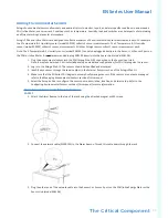
2. In the data panel, click the Status, Setting linke of the circuit breaker to configure. The Circuit Breaker Current
Alarm Setting dialog will display.
3. Select and enter the appropriate thresholds in amps and then click Save.
•
Lower Critical (A)
•
Lower Warning (A)
•
Upper Warning (A)
•
Upper Critical (A)
•
Reset Threshold (A)
Example when a reset threshold is useful…The current critical threshold for the input phase is set
to 19 amps (A). The current draw rises to 20A, triggering a Current Critical alert. The current then
continues to fluctuate between 18.1A and 20A. With the reset threshold set to 1A, the pdu continues
to indicate that the current on the input phase is above critical. Without a reset threshold (that is, the
reset threshold is set to zero), the pdu would de-assert the condition each time the current dropped to
18.9A, and re-assert the condition each time the current reached 19A or higher. With the fluctuating
current, this could result in a number of repeating SNMP traps, and/or an emailaccount full of repeat-
ing SMTP alert notifications
.
•
Alarm State Change Delay (samples)
If enabled, the PDU asserts any warning or critical condition only after a specified number of consecu-
tive samples that cross a particular threshold are generated. This prevents a number of threshold
alerts from being generated if the measurements return to normal immediately after rising above an
upper threshold or dropping below a lower threshold.
4. Repeat steps 1 - 3 for all circuit breakers.
External Sensors
The External Sensors section of the PDU Explorer displays connected sensors and the following information
about the sensor:
•
ID
•
Type
•
Status, Setting
•
Value
•
Serial No.
•
Aisle
•
Name
•
Description
•
Location
•
Action
Outlet Power Management
With the EN Series PDU you can customize each outlet and view all circuit breaker to outlet associations
through the Enlogic Web UI. On certain EN Series models, outlets can be remotely turned on/off.
Naming an Outlet
1. In the PDU Explorer, expand the Outlets Power Management folder by clicking the
icon.
2. Select the outlet to name. In the data panel, select the value field for the Outlet Name.
3. Delete the default name and type the new name.


