The Critical Component
EN Series User Manual
49
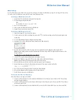
DNA Setup
To setup DNA mode on two PDUs, the user must (1) configure the PDUs for DNA Mode (
using CLI or Enlogic PCT
) and then
(2) connect the LAN Network cords and Ethernet cords between PDUs
To Configure DNA Mode in the CLI
1. Login to the CLI and enter the command ‘dev daisy dna’.
2. The following message will appear:
E801
System Reboot now, Are you sure? (Y/N)
3. Enter Y to confirm reboot.
4. After reboot, the PDU will be setup to DNA Mode.
5. Repeat this process for the second PDU.
To Configure DNA Mode in the PCT
1. Open the Enlogic PCT tool. Select the region.
2. Create a new conf.ini file by selecting the new button(
). Or edit an existing conf.ini file by selecting the load
button ( ).
3. Go to Config Settings>Device Configuration>Daisy Mode.
4.
Be default, this is set to QNA (Daisy Chain) Mode.
Select DNA. Select OK.
5. Save the new conf.ini file. Follow the steps below to upload the new Configuration file using the PCT.
Note:
the new Configuration can also be uploaded to the PDU using a USB, through the web interface, or the
Enlogic software.
To upload the new Configuration file using the PCT:
1. In the PCT Tool, go to Firmware Maintenance>Update Firmware.
2. Select the IP Address range of the PDUs to be configured for DNA. Select Discover.
Note:
The Read Community String must be the same as the PDUs.
3. When the PDUs are in the list, select the check box next to the IP Addresses.
4. Select the button next to the Config section and browse to the newly created conf.ini file.
5. Enter the username and password for those PDUs. Select Upload.
6. When the Configuration file is uploaded, the PDUs will reboot.
7. Both PDUs are now setup in DNA Mode.
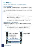
To Connect the PDUs for DNA Setup
After the PDUs are configured for DNA:
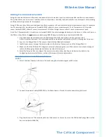
1. Connect an Ethernet cable from the Landlord LAN Network to the Ethernet port of the first PDU. This will have
limited access/permissions.
2. Connect an Ethernet cable from the Tenant LAN Network to the Ethernet port of the second PDU. This will have
full access to both PDUs.
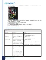
3. Connect an Ethernet cable from the Rs485-1 port on first PDU to the RS485-2 port on the second PDU.


