ENMET
Corporation
ISA-40M Oxygen Monitor
6
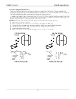
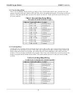
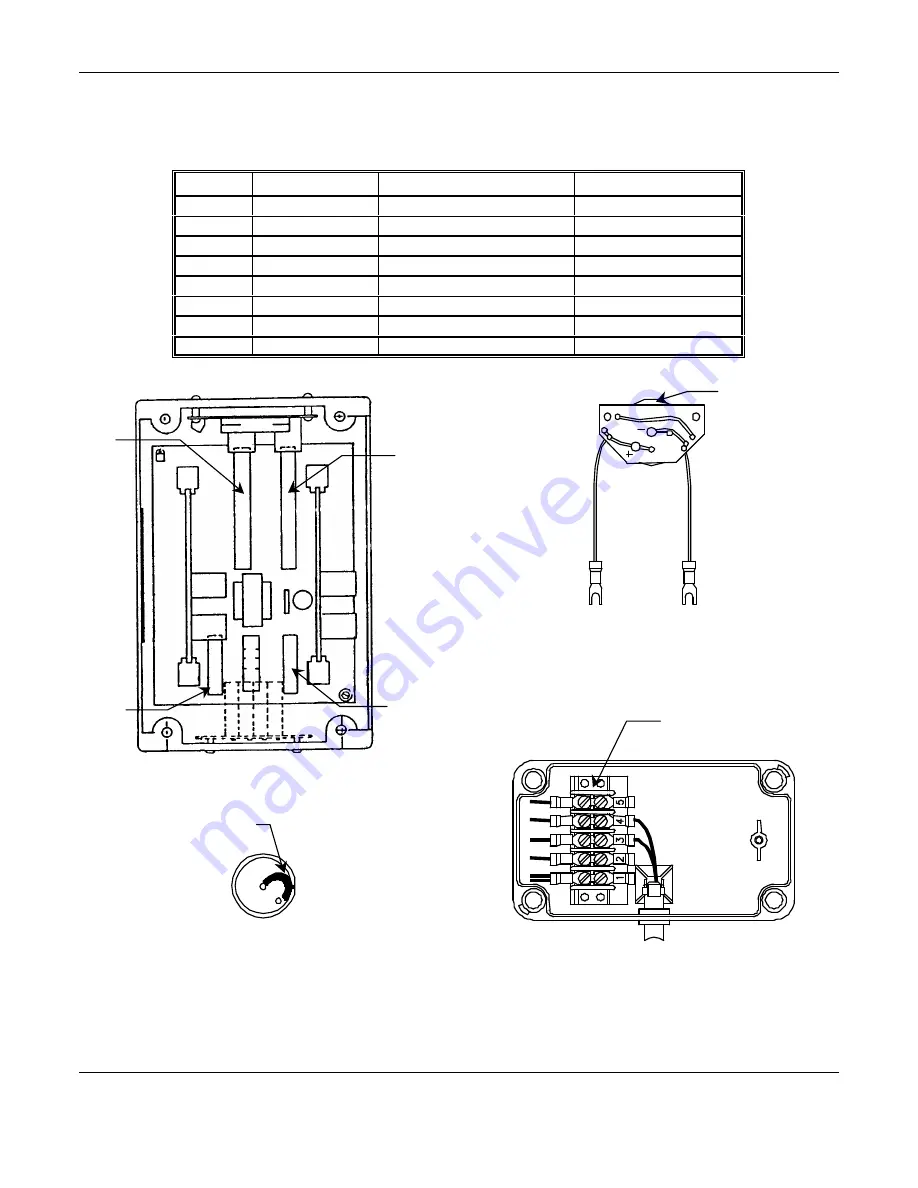
3.2.2 Remote Sensor Assembly Wiring
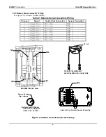
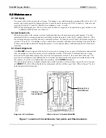
See Figure 4 for location of terminal blocks.
Table 2: Remote Sensor Assembly Wiring
Channel
Signal
Control Unit Connection
Sensor Connection
1
Oxygen Cell (–)
TB1 – 1 O2 –
TBS – 3
1
Oxygen Cell (+)
TB1 – 1 O2 +
TBS – 4
2
Oxygen Cell (–)
TB1 – 2 O2 –
TBS – 3
2
Oxygen Cell (+)
TB1 – 2 O2 +
TBS – 4
3
Oxygen Cell (–)
TB2 – 3 O2 –
TBS – 3
3
Oxygen Cell (+)
TB2 – 3 O2 +
TBS – 4
4
Oxygen Cell (–)
TB2 – 4 O2 –
TBS – 3
4
Oxygen Cell (+)
TB2 – 4 O2 +
TBS – 4
Figure 4: Interior View of Sensor Assembly
Internal View: Remote Sensor Assembly
TBS
Remove Shoring
Clip or Spring
Bottom View O2 Sensor
••
Center Pin – Negative
••
Outer Pin + Positive
O2 Cell Circuit Board
w/cell installed on circuit side
O2 Cell
TB4
TB2
TB1
TB3
T
B
3
T
B
4
T
B
2
T
B
1
T
B
5
TB7
ISA-40M Interior View


