background image

CD-1300-ST


ENMET 


Manual Revision Date – June 15, 2017


P a g e

 | 

3


Manual Part No. – 80003-134 


2.0 Features 

2.1 Display and Indicators 

The basic 

CD-1300-ST Series

 has a single green LED on the front panel which illuminates whenever the unit is operating.  This 

LED is on steadily when the measured concentration is below the high CO

2

 limit, and blinks whenever the concentration is above 

the limit. 
 
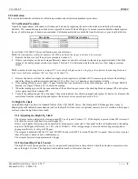
The standard factory high limit is 1000 ppm, but can be easily adjusted in the field.  The procedure for adjusting the high CO

2

 limit 

is described in Section 5.2. 
 
The display option adds a 4-digit liquid crystal display (LCD) to the front panel. The display shows the measured CO

2


concentration in parts per million (ppm). 1000 parts per million equals 0.1%. 
 

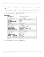
2.2 Specifications 

Operating principle 

Non-dispersive infrared (NDIR) 

Gas sampling method 

Diffusion or sample draw 

Measurement range 

0 – 2000 ppm CO

2

, Optional 0 – 5000 ppm 

Typical drift (per year) 

±75 ppm (@ 1200ppm) 

Accuracy 

±5% of reading or ±75 ppm, whichever is greater 

Repeatability 

±20 ppm 

Recommended Calibration 
Interval 

One Year 

Response time 

Less than 1 minute 

Operating temperature range 

0 to 50 



Operating humidity range 

0 - 90% RH (non-condensing) 

Storage temperature 

-30 to + 60 



Power requirements 

20 – 28 V

RMS 

AC, 18 - 30 V

DC


Power consumption 

Less than 2W @ 24 V

AC


Calibration adjustments 

Span only (offset electronically nulled) 

Calibration verification time 

10 minutes typical 

Dimensions 

5.2" x 3.2" x 1.4" 

Voltage output (linear) 

0 – 10 volts DC standard 

Current output (linear) 

4 - 20 mA (R

L




50

Warm-up time 

3 minutes 

Weight 

6.5 Oz. (0.35 Kg) 

Optional Digital Display 

4 digit, .35" LCD 

Optional 
High Limit 
Contact 

set point range 

0 to full scale 

contact polarity 

jumper selectable 

contact rating 

2A @ 24 V

AC


Operating life expectancy 

10 years typical 

Warranty 

12 months, parts and labor through repair or exchange 


N

OTE

:


All specifications stated in this manual may change without notice.


Summary of Contents for CD-1300-ST Series

Page 1: ...ENMET 680 Fairfield Court Ann Arbor MI 48108 734 761 1270 Fax 734 761 3220 www enmet com CD 1300 ST Series CO2 Sensor Transmitter Operation and Maintenance Menu ...

Page 2: ...ent 6 4 2 Altitude Correction 7 4 2 1 Altitude Correction Procedure 7 5 0 CALIBRATION 8 5 1 Verification Procedure 8 5 2 High CO2 Limit 8 5 2 1 Adjusting the High CO2 Limit 8 5 2 2 Optional High Limit Contact 8 5 2 3 Setting High Limit Contact Polarity 9 6 0 DUCT SAMPLING OPTION 10 6 1 Overview 10 6 1 1 Duct Kit Contents 10 6 1 2 Duct Kit Installation 10 7 0 TERMS AND CONDITIONS 11 7 1 Ordering In...

Page 3: ...ected verified and properly packaged at ENMET and delivered to the carrier in good condition When it was picked up by the carrier at ENMET it legally became your company s property If your shipment arrives damaged o Keep the items packing material and carton As Is Within 5 days of receipt notify the carrier s local office and request immediate inspection of the carton and the contents o After the ...

Page 4: ...aw Measurement range 0 2000 ppm CO2 Optional 0 5000 ppm Typical drift per year 75 ppm 1200ppm Accuracy 5 of reading or 75 ppm whichever is greater Repeatability 20 ppm Recommended Calibration Interval One Year Response time Less than 1 minute Operating temperature range 0 to 50 C Operating humidity range 0 90 RH non condensing Storage temperature 30 to 60 C Power requirements 20 28 VRMS AC 18 30 V...

Page 5: ...tion describes the external connections to the CD 1300 ST Series Wiring enters the chassis through the cutout in the center of the unit Figure 2 CD 1300 ST Series Component Location 3 200 2 103 1 600 1 103 0 000 0 000 0 406 2 003 2 753 3 562 5 200 CUSTOMER WIRING NOTE When connecting to ENMET CP 10 CP 60 LC 8 or other 3 wire type controllers 1 Preferred wiring for long runs use 4 wire cable connec...

Page 6: ...og output selector are connected with the shorting block a current output appears between the two terminals marked ANALOG OUTPUT The output current increases linearly from 4 mA at the low output threshold to 20 mA at the high output threshold The unit is shipped from the factory with the low output threshold at 0 ppm and the high output threshold at 2000 ppm See section 4 1 the Analog Output Range...

Page 7: ... it over the two pins of jumper JP4 see Figure 2 Section 3 3 The display if present will show SEL 1 The display if present will show SEL Momentarily closing a jumper selects which value to change If the wrong jumper is selected simply open JP4 to restart the unit and begin again 2 Select the low output threshold by momentarily closing JP1 If the display is present it will show the current low disp...

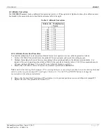
Page 8: ... concentration and record the reading in ppm 2 Multiply the reading by the scale factor corresponding to the operating altitude in the altitude correction table For instance if the unit is operating at an altitude of 4000 ft the scale factor from the table is 1 14 If the concentration reads 420 ppm multiply 420 times 1 14 giving 478 ppm Adjust the display to read 480 3 Remove the CD 1300 ST Series...

Page 9: ...table 4 If the reading differs by more than 75 ppm from the known concentration of the calibration gas use the UP and DOWN buttons see Figure 2 Section 3 3 to adjust the reading 5 When the reading agrees with the concentration of the calibration gas remove the shorting block on jumper JP2 and replace in its original position at jumper JP5 6 Turn off the calibration gas flow disconnect the gas tubi...

Page 10: ...per JP5 as shown in the table below Jumper JP5 Relay Operation OPEN normally closed opens above set point CLOSED factory default normally open closes above set point To open jumper JP5 remove the shorting block from the two pins and replace it so that it engages only a single pin of the jumper The shorting block should not be removed it is required during the calibration procedure ...

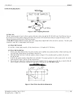
Page 11: ...s θ2 lengths of 1 8 ID tubing 6 1 2 Duct Kit Installation 1 Select a point along the duct where the probe assembly can be installed into unrestricted airflow without interfering with any internal duct components such as dampers radiators etc 2 Mark and drill the four holes for the duct probe as shown in Figure 4 The centerline must be parallel to the air flow through the duct 3 Install the duct pr...

Page 12: ...ction by the Seller confirms that the product is defective it will be repaired or replaced at no charge within the stated limitations and returned prepaid to any location in the United States The Seller shall not be liable for any loss or damage caused by the improper use or installation of the product The Buyer indemnifies and saves harmless the Seller with respect to any loss or damages that may...

Page 13: ...ce Request Form assists in the expedient service and return of your unit and failure to provide this information can result in processing delays ENMET charges a one hour minimum billing for all approved repairs with additional time billed to the closest tenth of an hour All instruments sent to ENMET are subject to a minimum evaluation fee even if returned unrepaired Unclaimed instruments that ENME...

Page 14: ... it Appears on Card RETURN SHIPPING METHOD UPS Ground UPS 3 Day Select UPS Next Day Air UPS ND Air Saver UPS 2 Day Air UPS Account FedEx Ground FedEx Air Express Saver FedEx Air Overnight Std FedEx Air 2 Day FedEx Air Overnight P 1 FedEx Account Insure Shipment Yes No Insurance Amount Product Name or Number Product Serial Number Describe Problem or Needed Service Warranty Claim Yes No CUSTOMER INF...

Reviews: