background image

CO-Guard 

ENMET 


Manual Release Date – June 8, 2017 

P a g e

 | 11 

Manual Part No. – 80002-044 


5.0 Maintenance


The 

CO-G

UARD

 maintenance menus that are accessed by pressing the 

M

ENU 

button and entering a valid access code.  The access 

code is set at the factory and may be changed by following the access code menu explained in section 5.5. 


5.1 Maintenance Menus 

C

AUTION

:


Do Not Attempt a Span Procedure Without Calibration Gas Applied to The Sensor

; if this is done, the instrument is 

forced into a calibration fault mode. 

 
Pushbutton switches control the


M

ENU

 and 

S

ELECT 

functions.  The 

M

ENU

 and 

S

ELECT

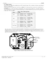
 button locations are indicated on the 

display panel, see 

Figure 3.

  The 

M

ENU

 button is used to display the various menu options and make incremental changes to 

numbers such as alarm points, calibrations gas, etc.  The 

S

ELECT

 button is used to select that option, set zero or span digit. 

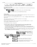
To enter the maintenance menu, press and hold the 

M

ENU

 button for 2 to 4 seconds 

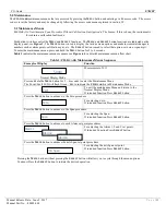
Table 3

 indicates the maintenance menu sequence see 

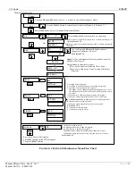
Figure 6

 for a detailed maintenance menu flow chart. 


Table 3: CO-G

UARD

 Maintenance Menus Sequence 

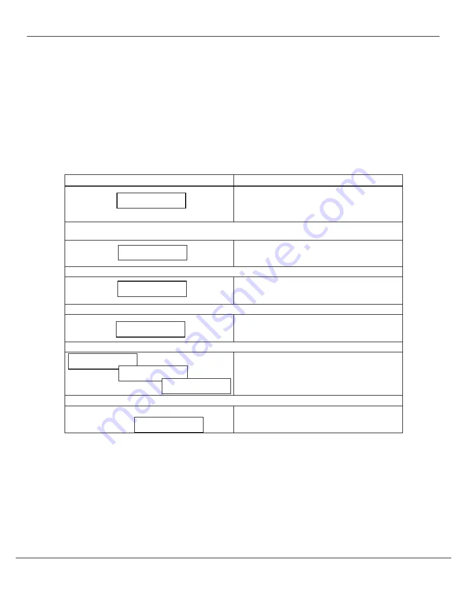
Example of Display 

Function 


Normal Display Mode 

Measurement of CO 
 

Press and 

hold

 the 

M

ENU

 button for 2 – 4 seconds to enter the Maintenance Menu 

The Power/Fault LED will flash Green – Red to indicate the 

CO-G

UARD

 is in Maintenance Mode 


To exit the maintenance Menu and return to the 
Normal Display Mode: 
If intended function Press 

S

ELECT

 button 

Press the 

M

ENU

 button to advance to the Zero procedure 


For adjusting Zero: 
If intended function Press 

S

ELECT

 button 

Press the 

M

ENU

 button to advance to the Span procedure 


For adjusting the Span: 
If intended function Press 

S

ELECT

 button 


Press the 

M

ENU

 button to advance to each Alarm set point procedures 


For adjusting the Alarm 1, 2 and 3 set points: 
If Intended Function Press 

S

ELECT

 button 


Press the 

M

ENU

 button to advance the mA Span set point procedure 


For adjusting the mA Span set point: 
If intended function Press 

S

ELECT

 button 


Pressing the 

M

ENU

 button without pressing the 

S

ELECT

 button will allow you to cycle through the menu options. 

You must Press the 

S

ELECT

 button to initiate the desired operation. 


5ppm  

Exit 

Zero 

Span 

mA Span 

Alarm1 

Alarm2 

Alarm3 

Summary of Contents for CO-GUARD

Page 1: ...ENMET 680 Fairfield Court Ann Arbor MI 48108 734 761 1270 Fax 734 761 3220 www enmet com CO Guard Compressed Air Line CO Monitor Operation Manual...

Page 2: ...16 5 2 5 Span Set 16 5 4 Sensor Replacement 17 6 0 REPLACEMENT PARTS 18 7 0 TECHNICAL DATA AND SPECIFICATIONS 18 List of Tables Table 1 Relay Failsafe Settings 8 Table 2 Factory Alarm Set Points 10 T...

Page 3: ...mpany s property If your shipment arrives damaged o Keep the items packing material and carton As Is Within 5 days of receipt notify the carrier s local office and request immediate inspection of the...

Page 4: ...rd exposing the interior of the enclosure See Figure 1 for location of features Feature Description Display A single line 8 character LCD with backlight Indicates the level of gas detected by sensor T...

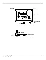
Page 5: ...l CO GUARD Features Figure 1a Optional REGULATOR AND SAMPLE AIR HOSE Regulator Female Quick Release Fitting to Inlet Port NPT Select Menu Input Port Audio Alarm Strain Relief Visual Indicators Alarm1...

Page 6: ...surface of the enclosure interior Features are shown in Figure 2 Feature Description Relay Terminals This group of terminals is located on the Circuit Board For the contacts for each of three alarm re...

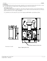
Page 7: ...nt the CO GUARD instrument on an appropriate vertical surface leaving room for lid to be opened using the mounting holes provided Avoid areas with excessive vibration or temperature extremes The holes...

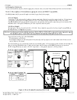
Page 8: ...to the Power Input Terminal TB1 and the Ground screw See Figure 4 for location WARNING Continuous gas detection and alarm systems 110VAC 220VAC 24VDC 12VDC powered become inoperative upon loss of prim...

Page 9: ...sition Alarm 1 J14 K1 Relay 1 NO Normally Open J14 K1 Relay 1 NC Normally Closed J14 K1 Relay 1 COM Common Alarm 2 J15 K2 Relay 2 NO Normally Open J15 K2 Relay 2 NC Normally Closed J15 K2 Relay 2 COM...

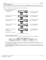
Page 10: ...acter in the display may flash a letter indicating the instrument status See the Section 4 1 1 below 4 1 1 Typical Start Up When power is supplied to the CO GUARD the instrument will display the follo...

Page 11: ...m see Section 4 2 1 Display indicates mA Span range Full Scale Press MENU button Display returns to CO measurent To temporally disable audio alarm see Section 4 2 1 Operational Display Flow Chart 4 2...

Page 12: ...Figure 6 for a detailed maintenance menu flow chart Table 3 CO GUARD Maintenance Menus Sequence Example of Display Function Normal Display Mode Measurement of CO Press and hold the MENU button for 2...

Page 13: ...red digit and moves to next digit See Section 5 2 5 To return to Normal Gas Display Press MENU button until EXIT is displayed Then press SELECT button OR Zero Cal OK If the Zero signal is not within P...

Page 14: ...other It is recommended that the Zero procedure be done prior to the Span procedure ENMET recommends at least quarterly calibration of the CO GUARD instrument Calibration equipment is available from...

Page 15: ...D will monitor the zero reading for stability If the reading stabilizes within the pre programmed perimeters an automatic zero adjustment will be made Cal OK appears on the display and in 1 2 seconds...

Page 16: ...the Span is successful Cal OK appears momentarily then will advance to Alarm1 menu If the sensor is outside of acceptable parameters Bad Span is displayed If the sensor did not respond an incompatibl...

Page 17: ...U button until to display Span is displayed 2 Press the SELECT button to initiate the mA Span menu 3 Press the MENU button to change the digit indicated by the underscore cursor 4 Press the SELECT but...

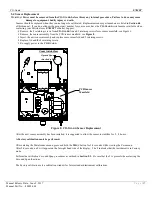
Page 18: ...ifold see Figure 8 Insert the new sensor assembly and replace sensor manifold and 2 retaining screws Replace lid and the 4 retaining screws Re supply power to the CO GUARD Figure 8 CO GUARD Sensor Rep...

Page 19: ...l Data and Specifications Electrical Power 15 Amp fused branch circuit 100 240 VAC 0 45A 50 60 Hz 0 6A 24VDC Storage and Transport Temperature 20 to 60 C 4 to 140 F preferred 0 to 20 C 32 to 68 F Rela...

Page 20: ...ill be repaired or replaced at no charge within the stated limitations and returned prepaid to any location in the United States The Seller shall not be liable for any loss or damage caused by the imp...

Page 21: ...your unit and failure to provide this information can result in processing delays ENMET charges a one hour minimum billing for all approved repairs with additional time billed to the closest tenth of...

Page 22: ...it Appears on Card RETURN SHIPPING METHOD UPS Ground UPS 3 Day Select UPS Next Day Air UPS ND Air Saver UPS 2 Day Air UPS Account FedEx Ground FedEx Air Express Saver FedEx Air Overnight Std FedEx Air...

Reviews: